LEGO®-Horizon-Adventures--Bringing-Terr
https://www.youtube.com/watch?v=heoXRhQv8cs
Hello everyone, welcome to my talk and thank you for coming.
My name is Giang, pronounced with a z and I am an engineer of the CoreTech team at Studio GoBo and I am representing the team here today to tell you the story of how we bring the terrain of the game Lego Horizon Adventures to the Nintendo Switch.

So you may have heard I say the word story, and that is exactly what we're having today. This is not your usual success story talk in the sense that I won't be telling you,

I do this, I do that, this will lead to success, etc, etc. But rather it focuses on iterations

about what we did to solve a particular problem to ship for the Switch platform.

This involves a couple of failed experiments as we found some assumptions didn't work as we expected. So ultimately, I hope that what we discovered may be helpful for you if you ever encounter something like this.

So without further ado, let's embark on our LEGO terrain adventures.

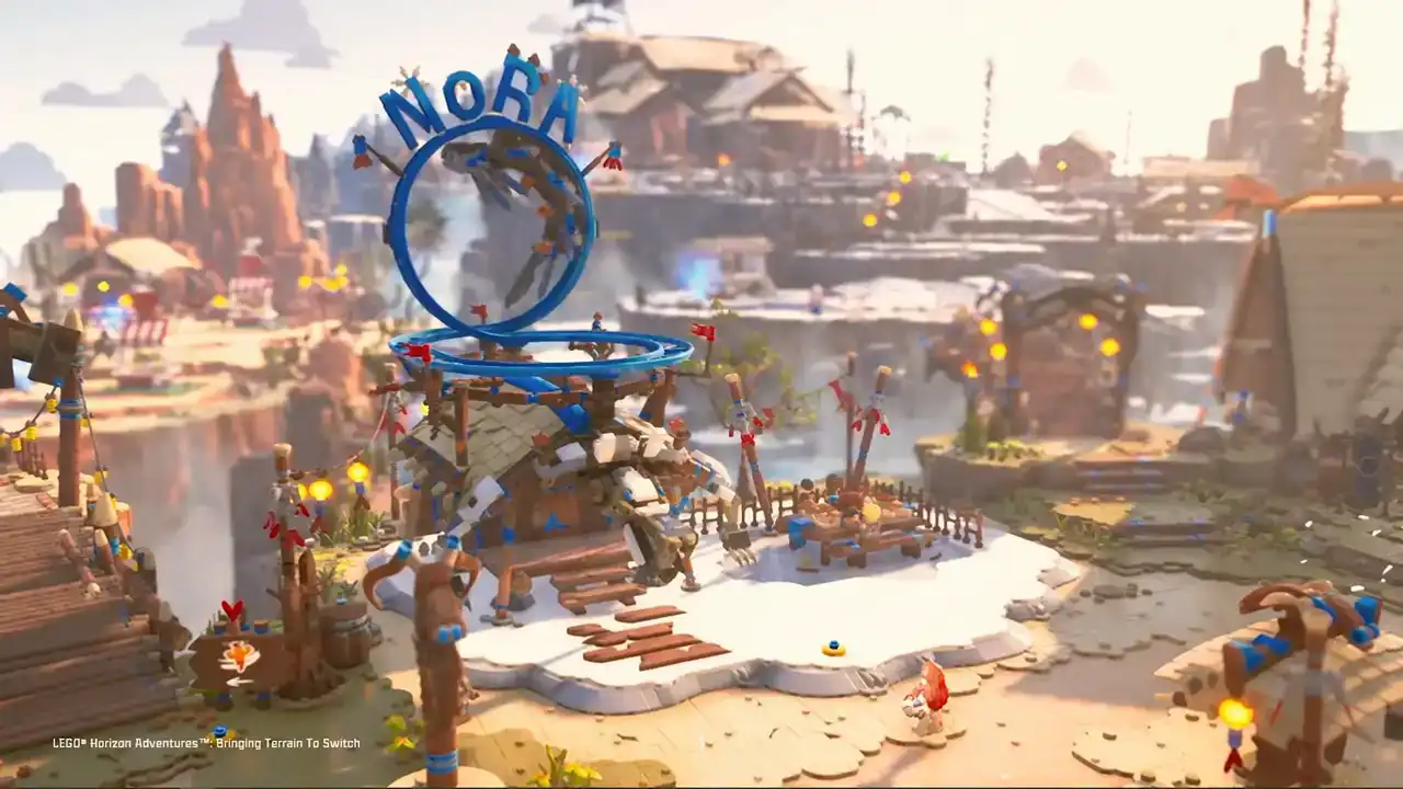
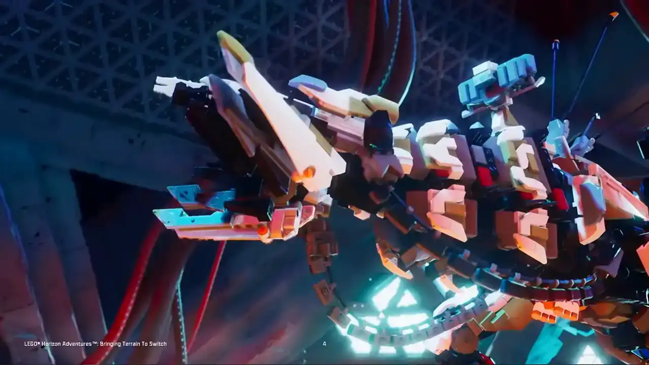
So now first let's start with a few gameplay footage of the game taken from the Nintendo Switch.
Oh, my God.
Okay.
I hope you liked it. Yeah, I hope you liked what you saw. It's pretty if I wouldn't say so myself. Now, the developer, we, Studio Global,
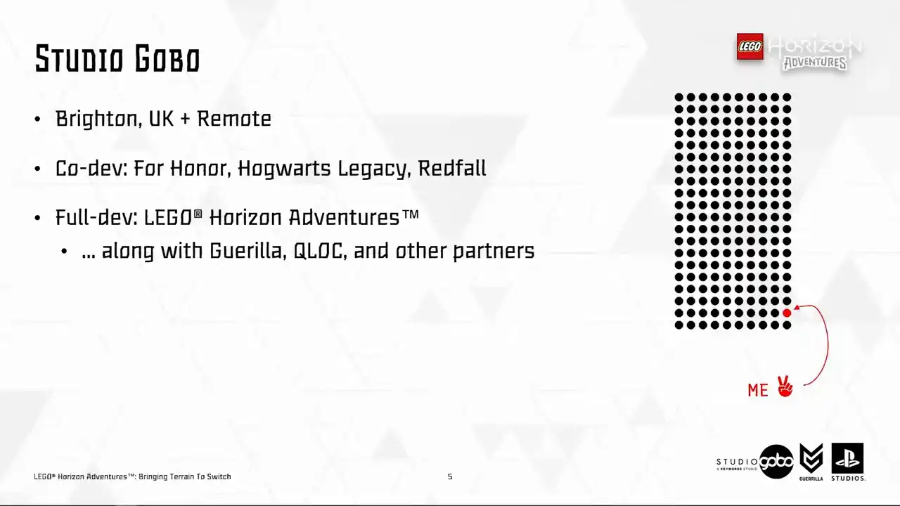
are a team based in Brighton in the UK with many members working remotely inside and outside of the UK. We co-developed many titles before, both with Legal Horizon Adventures. We did something different, being the full developer alongside our colleagues at Guerrilla, QLog and other partners.
As for me, I am from Hanoi, Vietnam. In my first half of my career, I was a gameplay programmer working on some mobile games. and when I moved to the UK, I started to work on lower level stuff and I started to enjoy it.
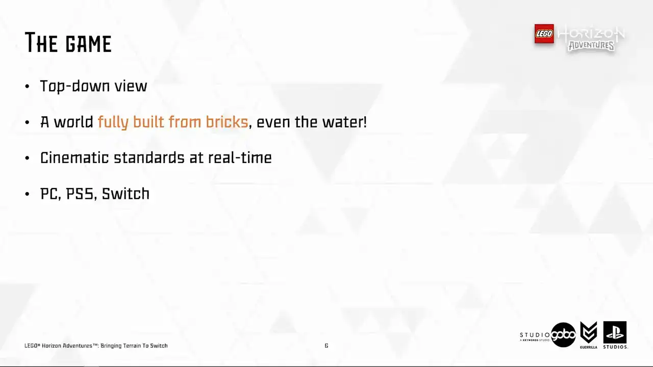
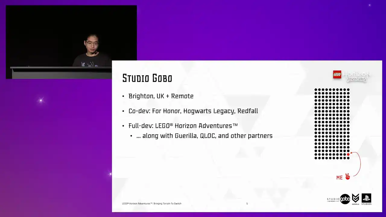
So as you saw from the game footage, LEGO Horizon Adventures features a top-down view looking over a world built fully from LEGO bricks and yes, even the water is also brick-based.
What we set out to achieve is the cinematic standards at real time So the hope is that the player is immersed in a miniaturized and realistic brick-built world.
So the platforms that we target are PC, PS5 and Nintendo Switch using Unreal 5.3.
So now, before getting to the actual problem-solving part, let me take you through how the terrain was built in Little Horizon.

adventures. So to begin, we cannot go down the route of many LEGO games before us did, but with the LEGO minific being placed into the usual game setting, if you get what I mean,
so our art direction is built, everything is built from brick, so what we want is essentially
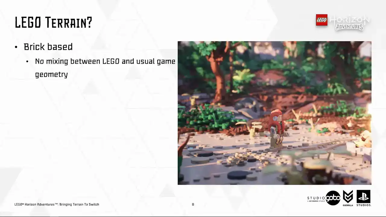
horizon terrain in brick form. Initially, we wanted to use uniquely handcrafted terrain models like this, but these were quickly dismissed due to it takes a lot of effort to make, and each model can easily take months to build.
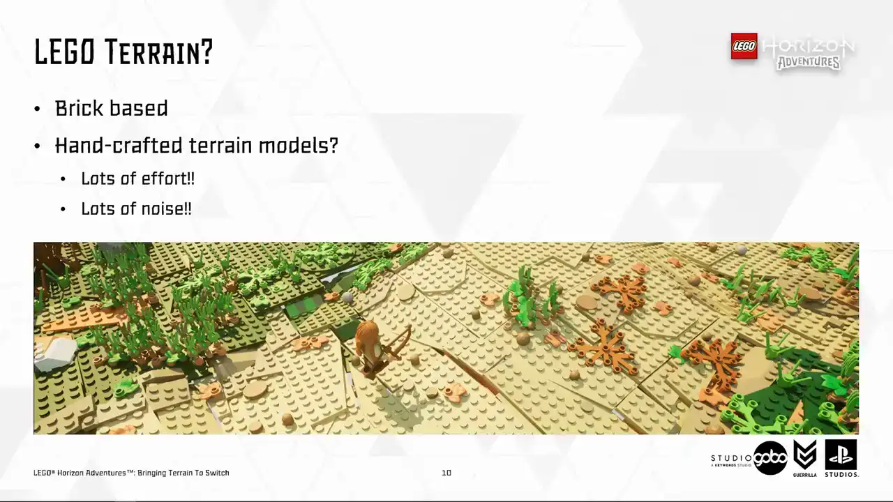
And also, it creates a lot of noise looking from the gameplay camera.
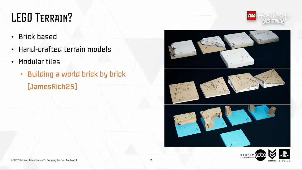
So our artists opted for an approach relying on modular tiles These modular tiles are snapped together using strict rules on size and angles It's quite a long story how we ended up designing the terrain this way in the perspective of art direction,
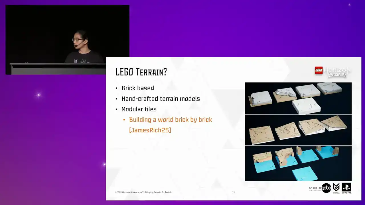
which my colleagues James and Rich covered in their GTC talk.
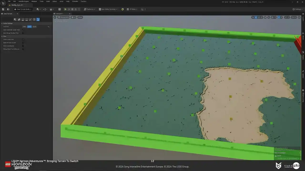
But anyway, going back to our problem, hand-placing terrain tiles is an exhausting and boring process. So to assess that, we have a terrain tool that lives alongside other Unreal Engine level design tools. It supports painting-style interactions. So with this tool, artists and level designers can paint terrain patches in different tile types and tile sets that's designed for each biome. I will get into this later.
And the important thing is that they have instant feedback so that they can do experiments and explorations easily and quickly.
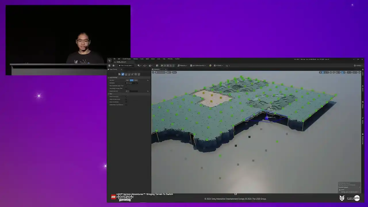
So here's how it looks in action.

Right, that was the terrain tool from user's perspective.
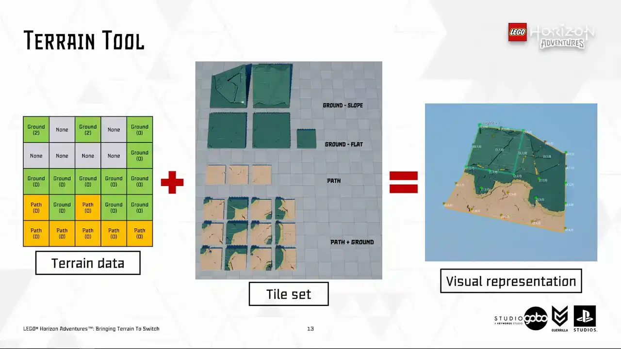
From a slightly more technical perspective, the tool output grid data, as you can see in the left hand side, it still see coordinate the height and the type of each corner of the tiles. This grid data is persistent and is what the terrain tool operates with under the hood. So we store this data in Actives called the terrain patches. This data determined which kind of visual does a tile have.
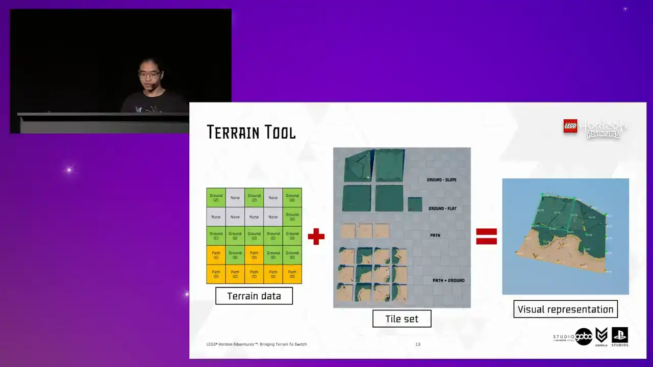
Using the tile data and the tile set, we can generate the final terrain representation using this data. So on the far right, you can see the final terrain representation with the tile corners annotated,
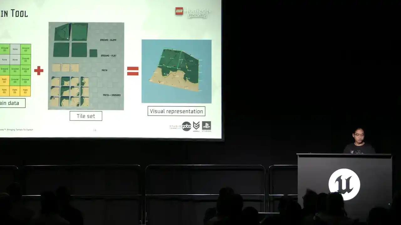
with a few example tiles we use to construct the terrain patches taken from the tile set in the middle. So a tile set basically contains configurations for what mesh to use for each height combination,
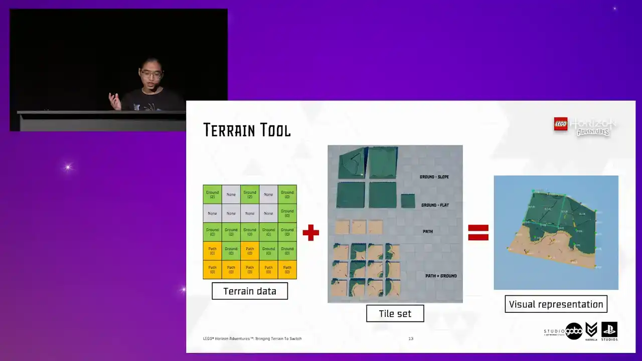
and to avoid repetition, each of these types have their own variances as well.
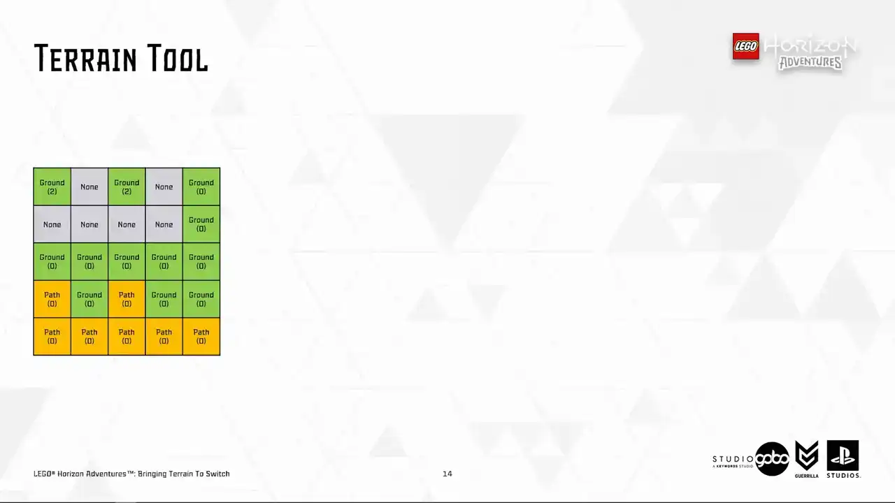
So now let's get other stuff out of the way and let's take a look at a few tiles to demonstrate the idea. We can see this tile has three corners being path and one corner being ground. So we should use a tile looking like this. And so on for this tile, same principle, different mesh.
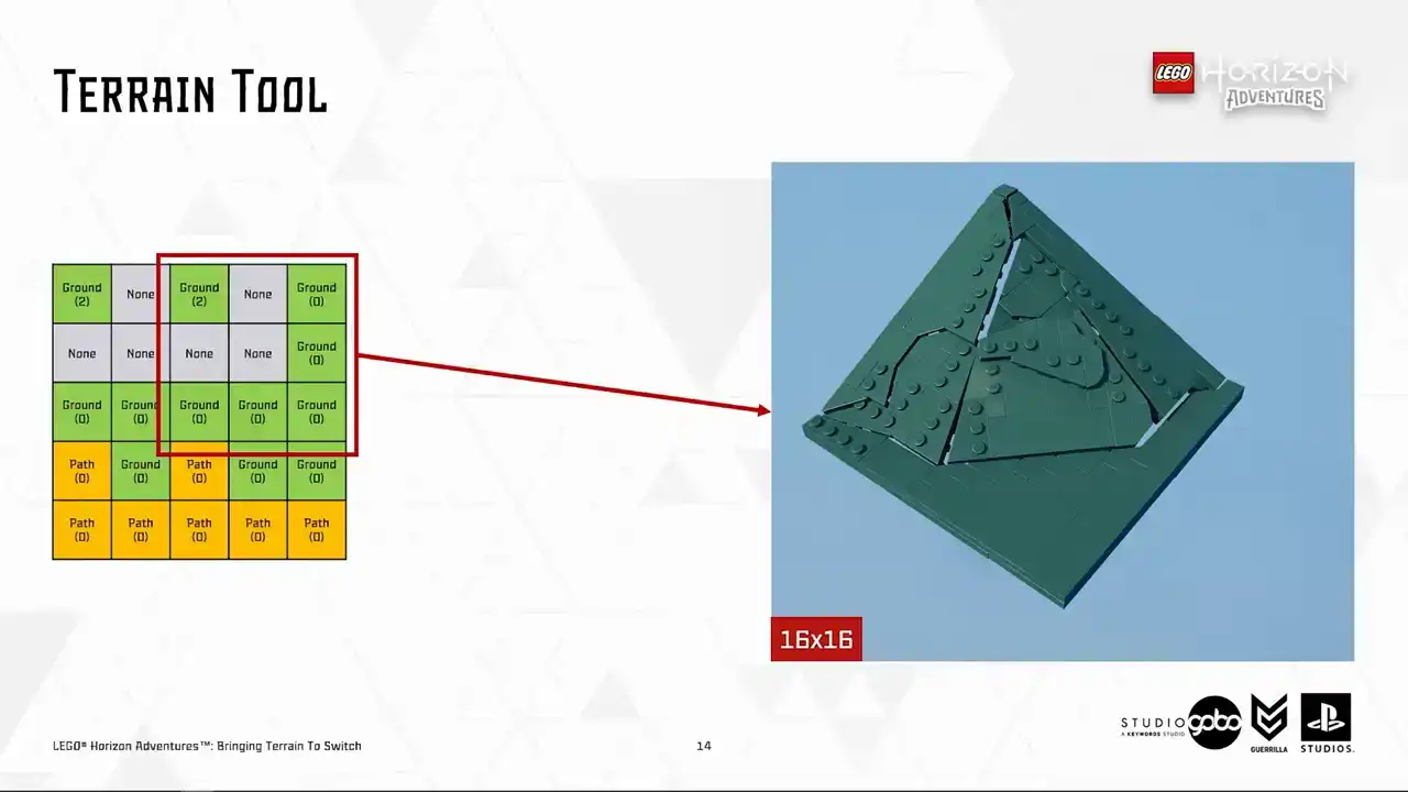
We also have a larger tiles with 16 by 16 or 32 by 32 dimensions as well. For example, this one. Notice that this is a case where a corner is higher than other corners.
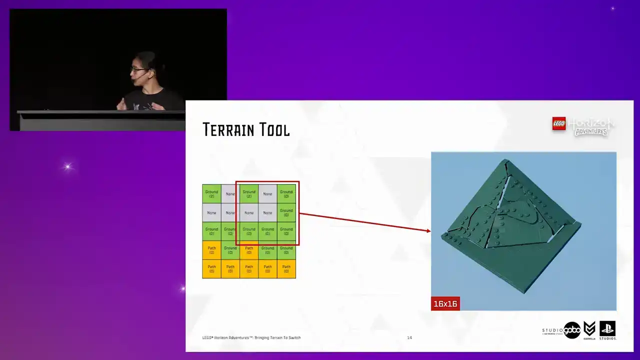
So a slope mesh is chosen. So same principles are applied for opposite cases where we want to create more pronounced edges of the terrain by just lowering the height.
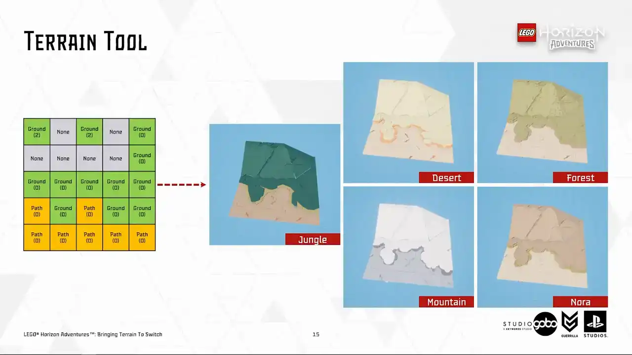
Another benefit of having terrain data splitted from representation is that we have a few tile sets that represent different biomes in the game, like you see here, so our designers can re-theme
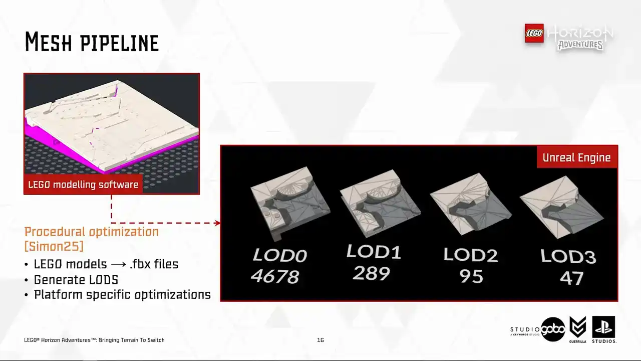
the terrain patches instantly. Now, let's take a closer look at the tiles. The terrain tiles like all other geometry in the game is powered by the same mesh pipeline. Behind this pipeline is some procedural Houdini black magic. If you're interested, I would recommend checking out my colleague Simon's talk about this topic. But for us,
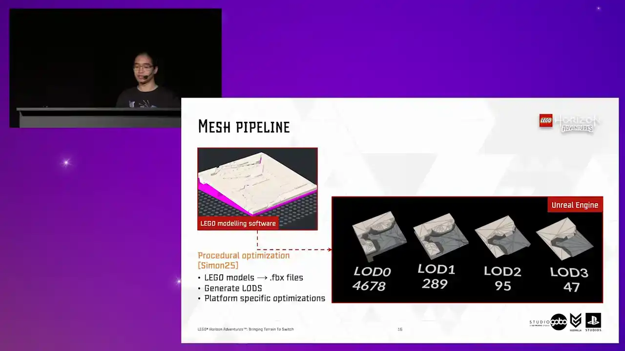
all we care about is that it generates an optimized mesh for us from the models being built inside a specialized Lego modeling software. The generated mesh lot zero is
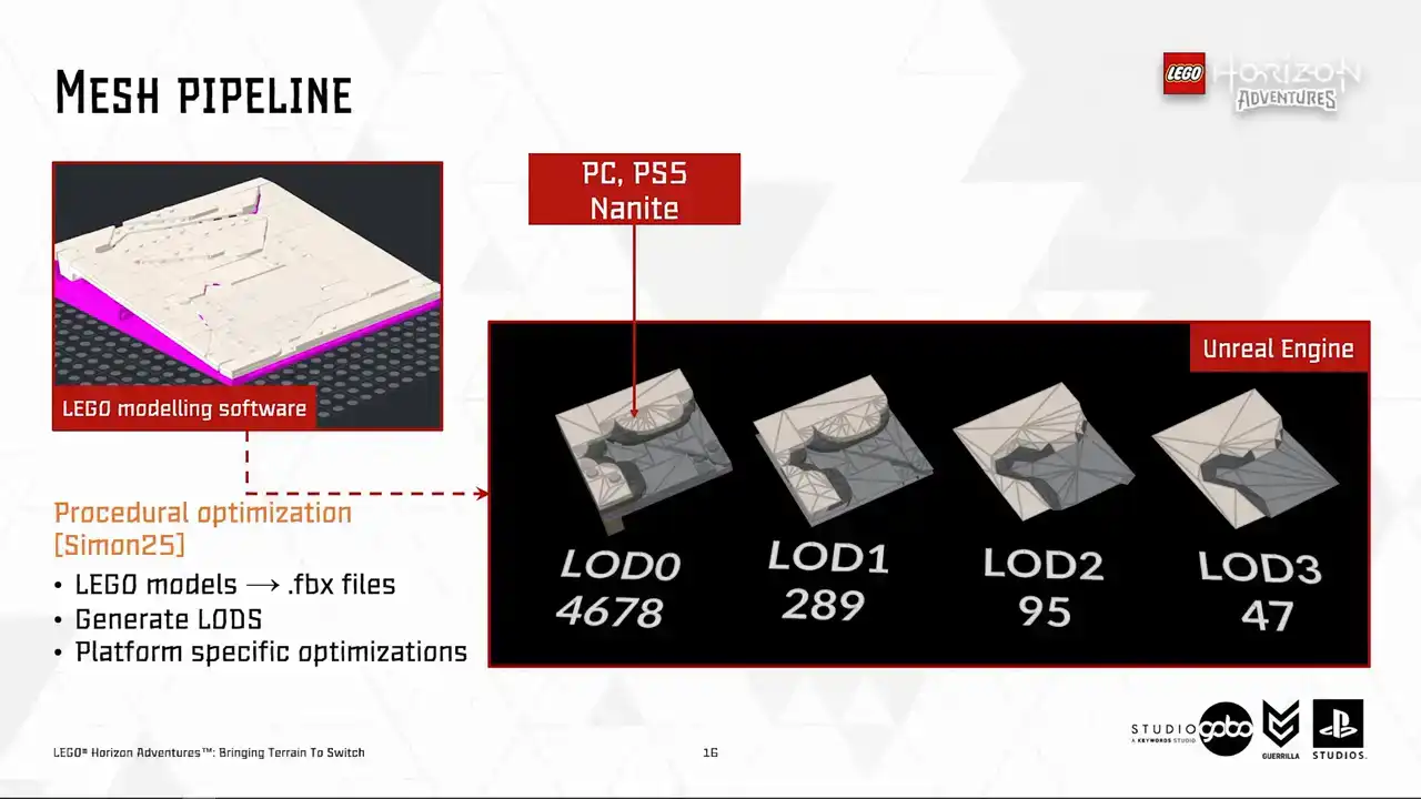
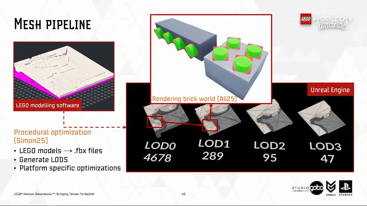
used for high-end platform where we leverage the cool new stuff like Nanite and Lumen while for switch we use HeigerLots starting from lot one and the traditional ways of rendering by issuing draw calls. So you may notice that Heiger
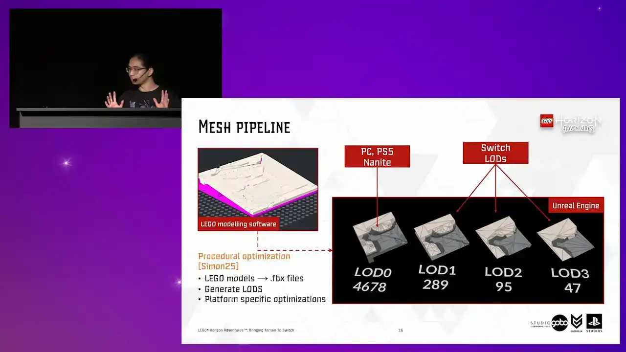
the Lord's geometry do not have the trademark Lego studs. Because for Switch, we render the studs by ray tracing into camera facing billboards in a separate pass in one draw call Instead of rendering it does geometry naively This is covered by my colleague Ali in his Digital Dragons talk
focusing on the rendering side of the game.
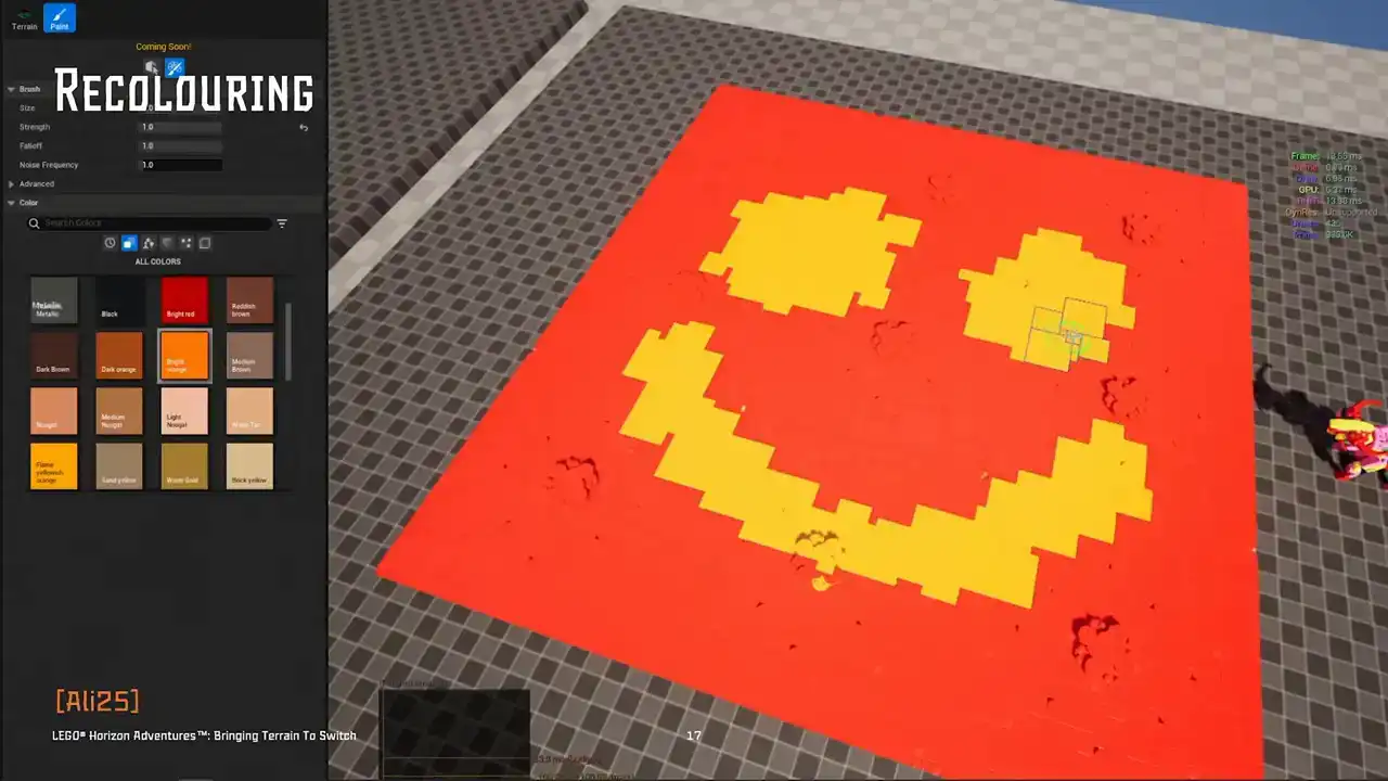
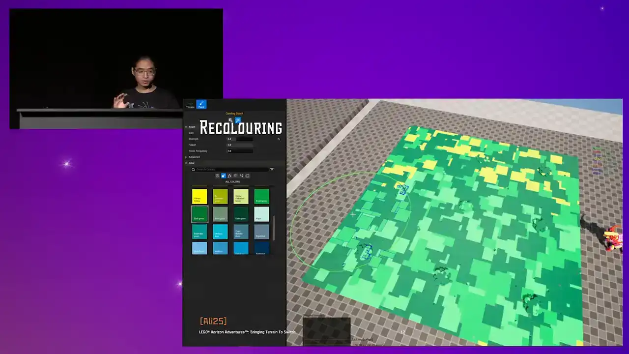
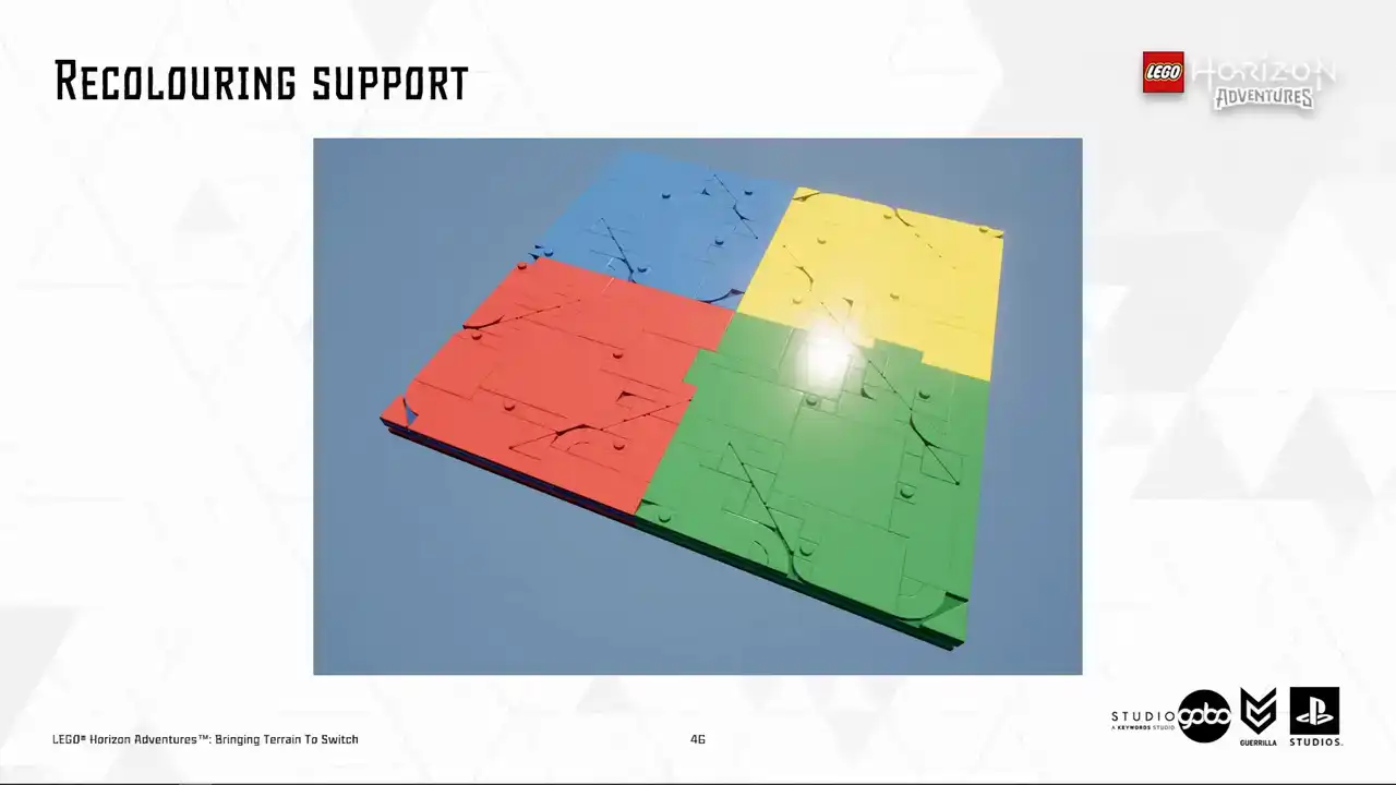
Next up, the Turian patches can also be painted on top using the recolouring tool. The tour supports brush style painting and bucket style painting. And these custom colors can also be saved as color presets to reuse later.
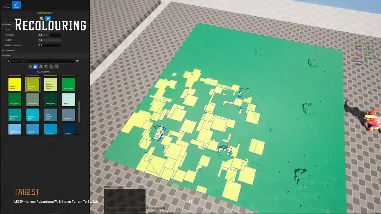
Recoloring basically allows more visual variety, but the artists don't have to duplicate the model assets. This feature, again, is not limited to the Turian models, but all Lego models in the project.
At the moment, we will not dig any deeper into how this works. Ali's talk already covered this in depth, but we will revisit this later in this talk. So please remember recoloring is a cool piece of tech.
So for now, it's enough to say our artists have several tools
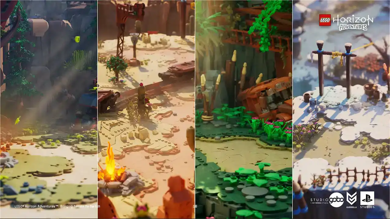
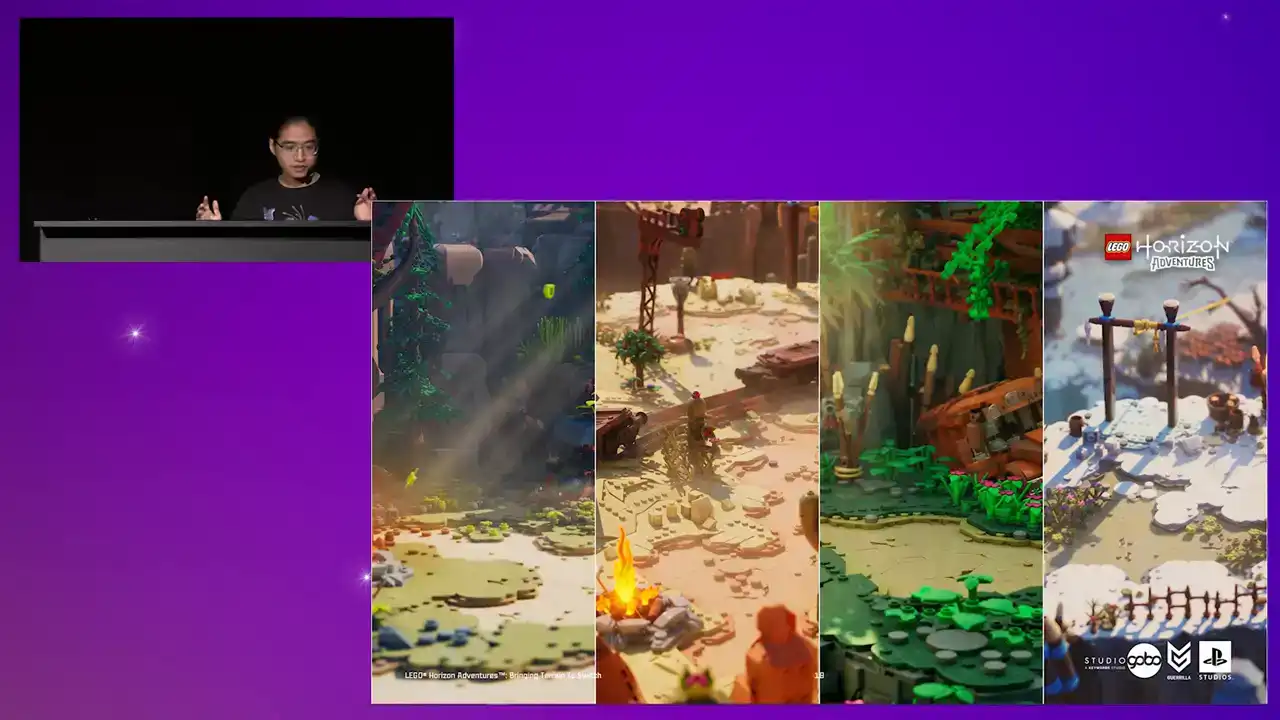
to achieve visual varieties for the terrain. They have biome-specific tile sets where they can apply visual identity to each biome
using a dedicated color palette and even shapes of bricks.

For example, the forest and Nora regions use softer and more rounded brick tiles for more friendly feel, while the desert and jungle use more angular shapes. And on top of this, for each level,

the color can be painted over without adding more stress on managing the tile models and the tileset library.
Okay, that's a quick summary
of how we built the terrain for this project. The terrain tool is widely used by level designers and environment artists and it massively sped up the work comparing to hand-placing tile models by hand.
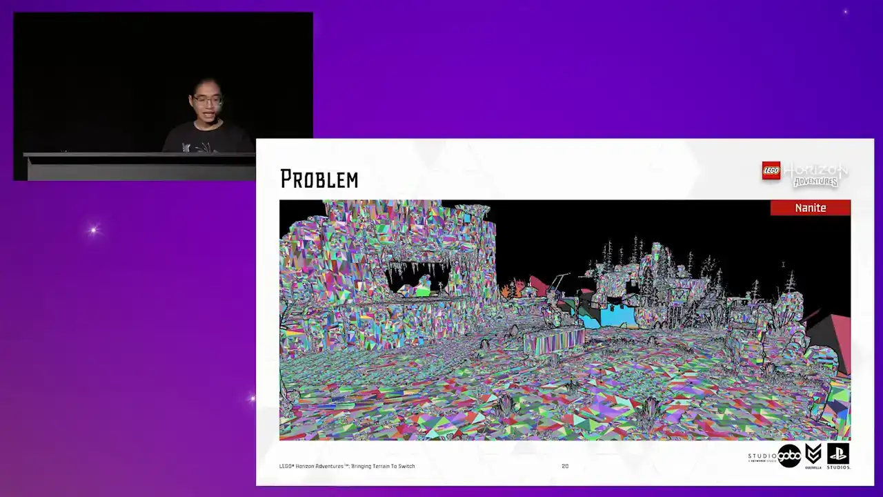
So on high-end platforms, again, we use Nanite, which does a lot of heavy lifting for us.
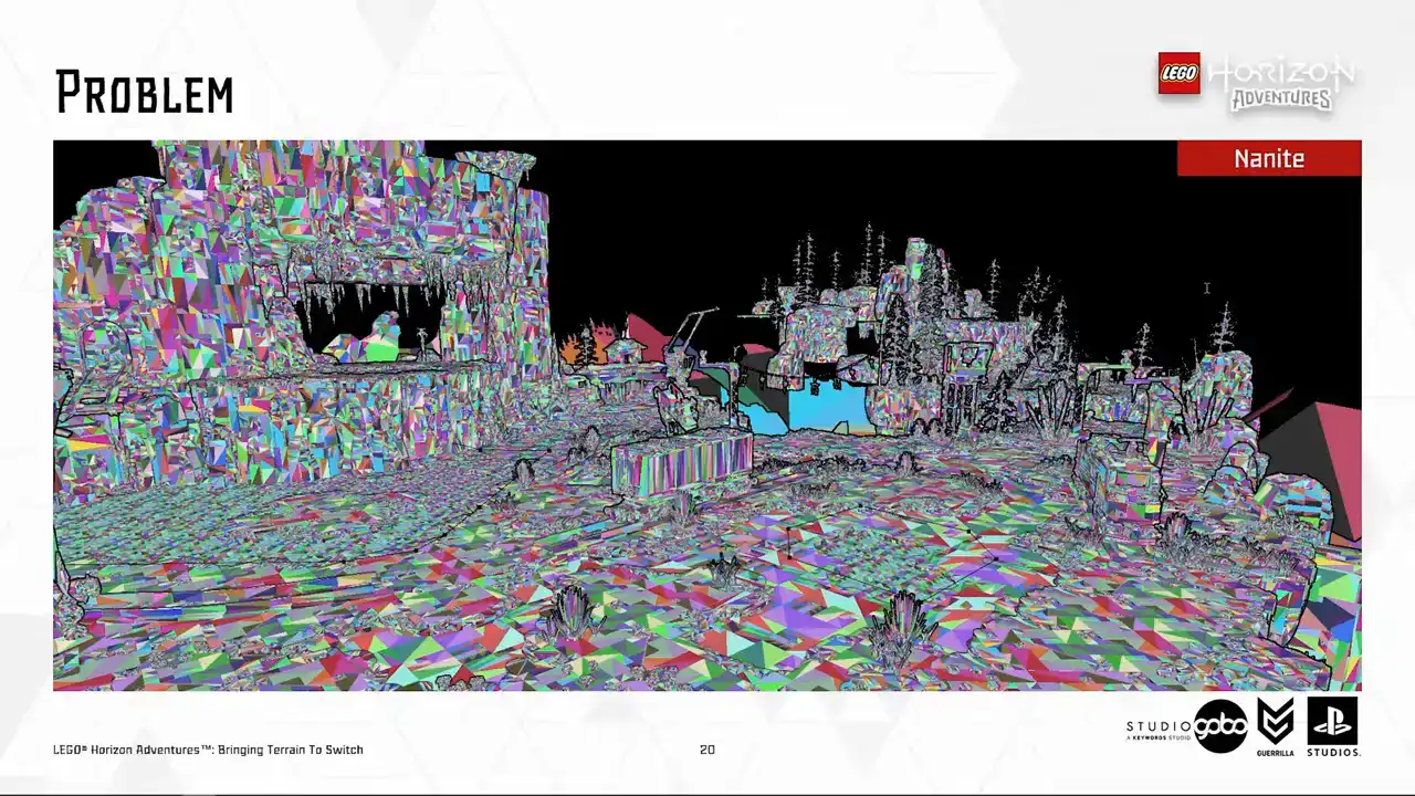
So essentially, it allows us to not having to worry about polycount or draw call or having overlapped models.
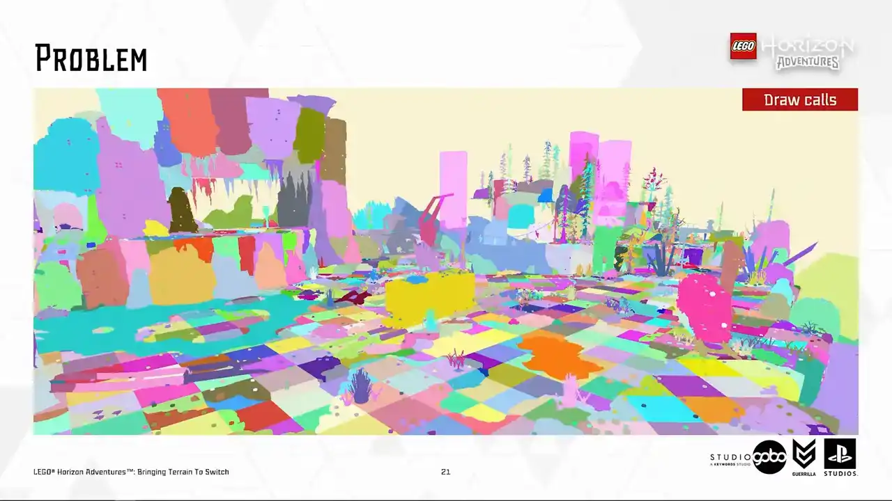
But on switch, as you can see here in our draw call visualization,
you can see that there's a lot of unique draw calls. And sometimes draw call count on switch

is very, very high, reaching a thousand draw calls. And terrain, like you see here, plays a good part of this due to each terrain patch consists of many individual tiles.
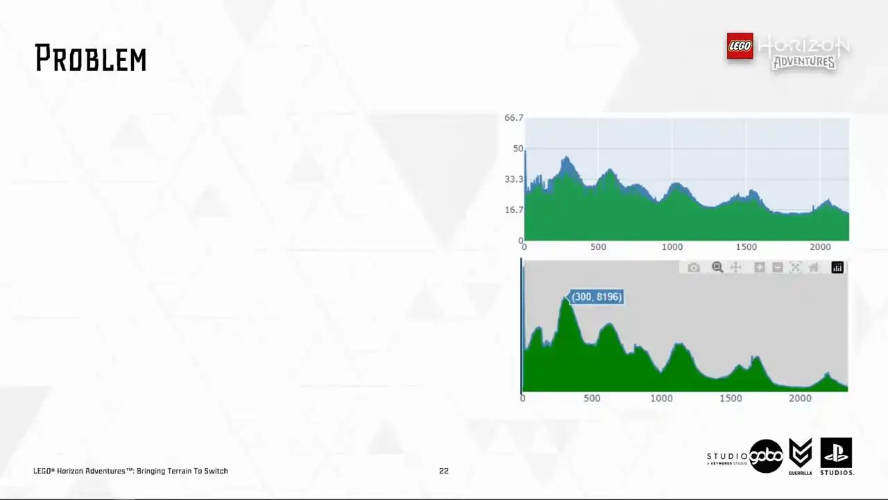
So here's a screenshot of our automated performance dashboard. The top is render thread time and the bottom is draw call. So this shows a correlation between these values. So these graphs indicate we would like to keep draw call counts under 2.5 thousand to reduce threats on the render thread while leaving some head rooms for the render thread to do other tasks. So this is something that we need to sort out. And while doing so, we must keep the usual workflow unchanged because the last thing we want to do is to have artists rebuilding different levels for different platforms. And not that we can afford to do so either
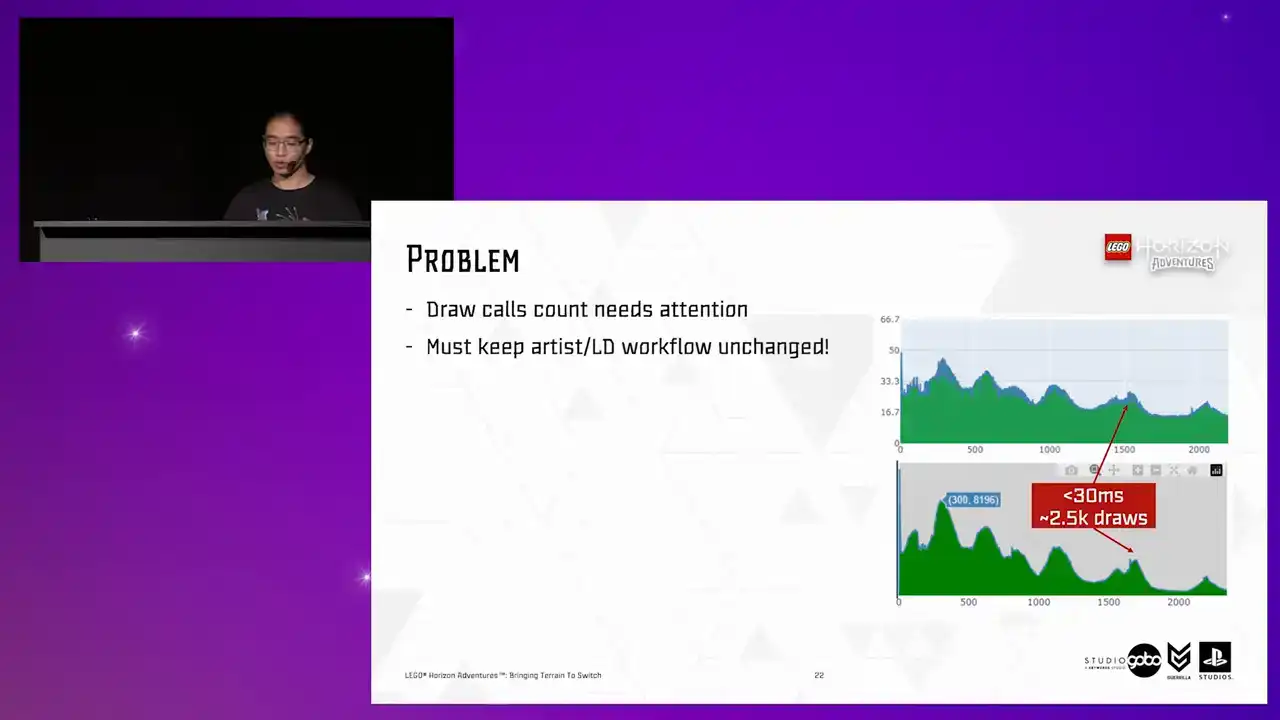
because many levels have already got the terrain almost finalized at this point, with all things considered like the Vista and the PlaySpace.
So now you're somewhat familiar with the relevant background information.

It's time for the main part of the talk, the terrain optimization.

So to begin with, our artists did a lot of work to bring down the draw goal counts. They designed the level for the switch first, and then they scale up to more capable platforms, which is the good mentality to start with. To do that, they made the most use of the fixed camera angle, so they used larger tiles where possible. For example, they used 32 by 32 or 16 by 16 tiles instead of 8 by 8 tiles. They also did a lot of manual iterations
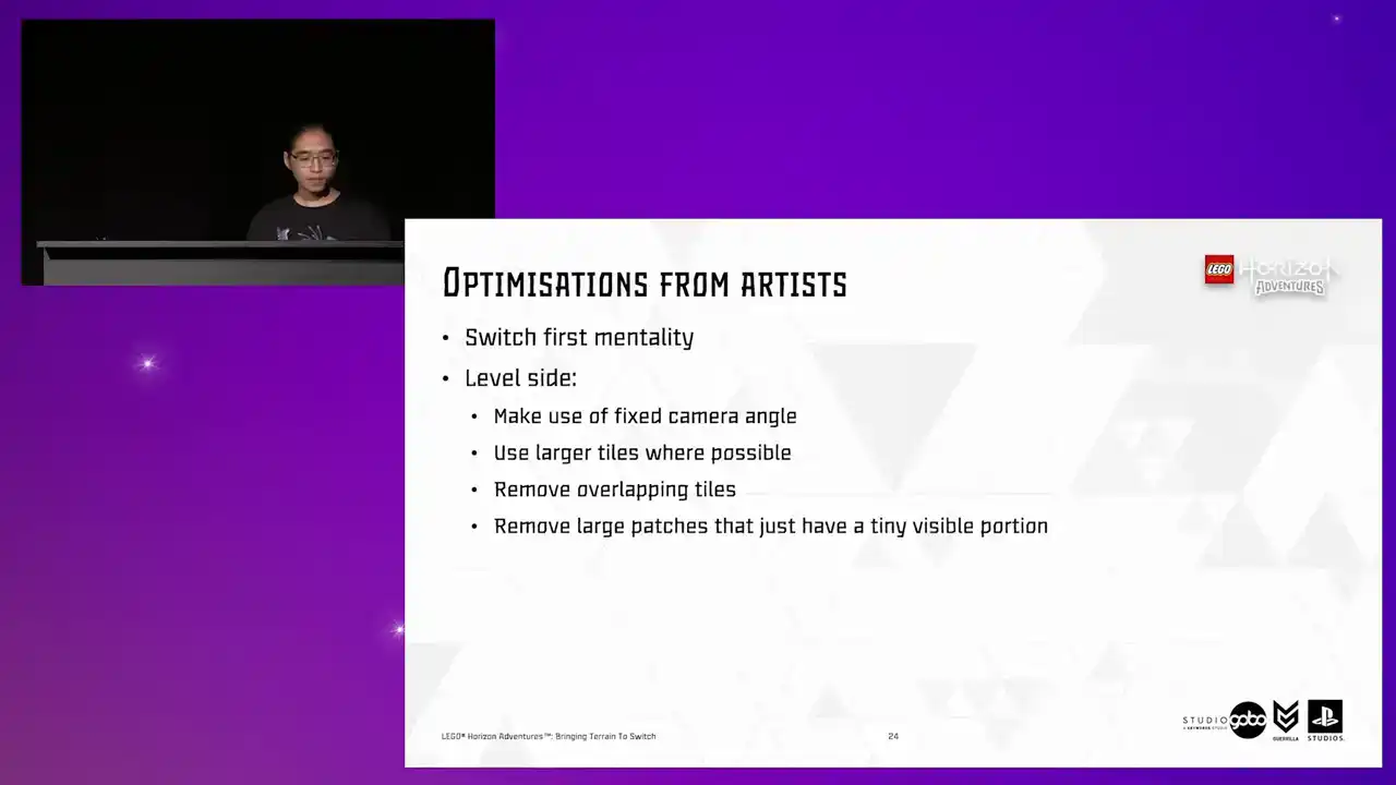
to keep the number of overlapping Turin patches or large patches with a tiny visible portion to the minimum. So up to this point, you can tell our artists worked under a lot of constraints, but they were able to optimize the drawcode count to around 5.6K.

Very impressive, given the initial numbers like 8K, but still very off target.
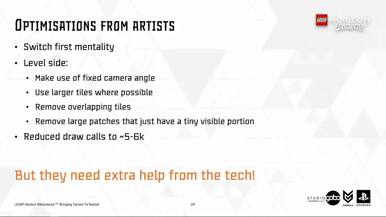
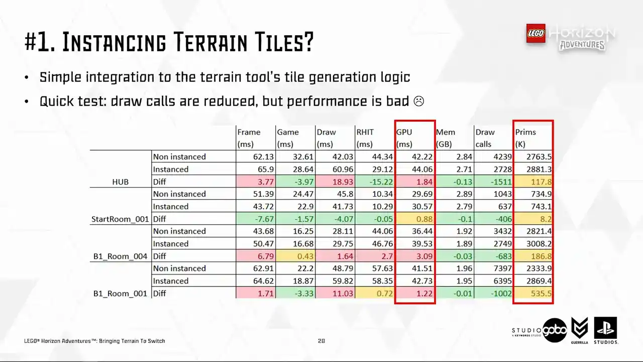
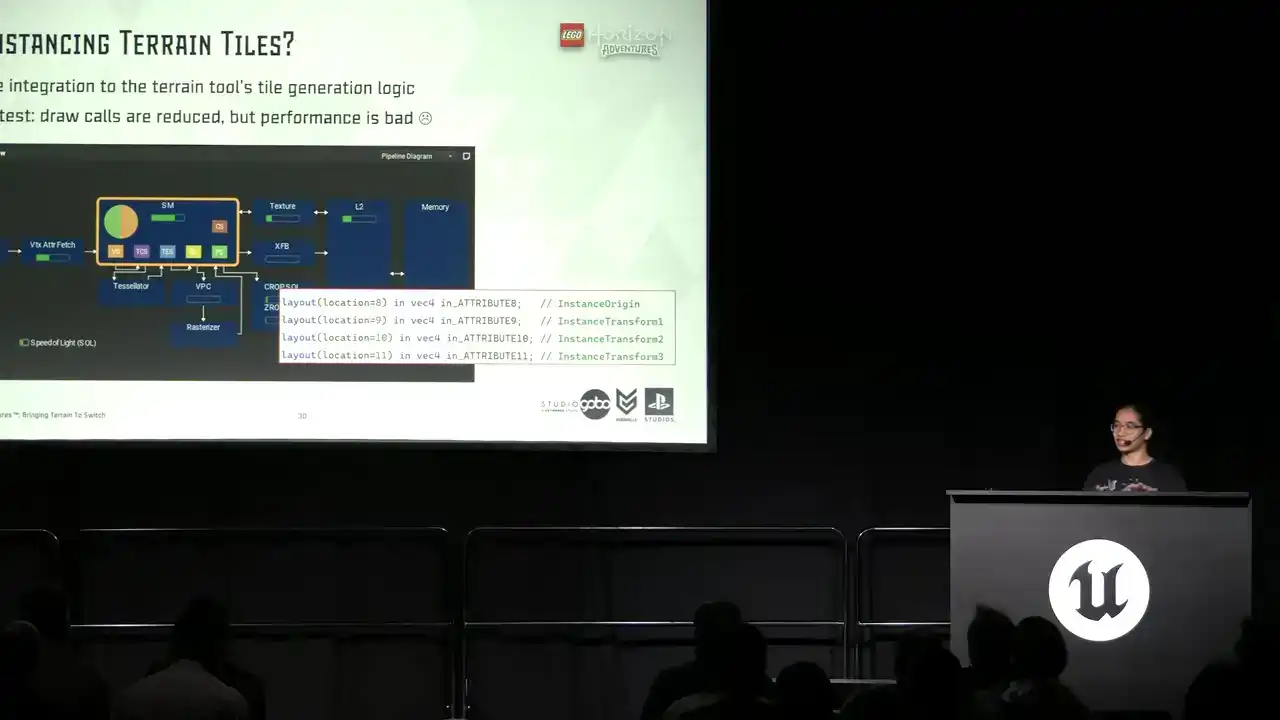
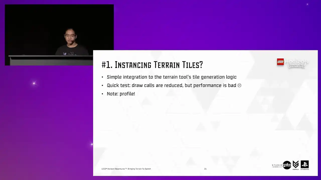
But there only so much that they can do before visual quality starts to degrade so they needed extra help from us engineers So the first idea we had obviously to reduce local instant tiles This is simple to integrate because we already have the terrain tool working on the patch data, so instead of spawning different static mesh components, we can just spawn a single hierarchical instant static mesh component and containing all the instances of a tile.
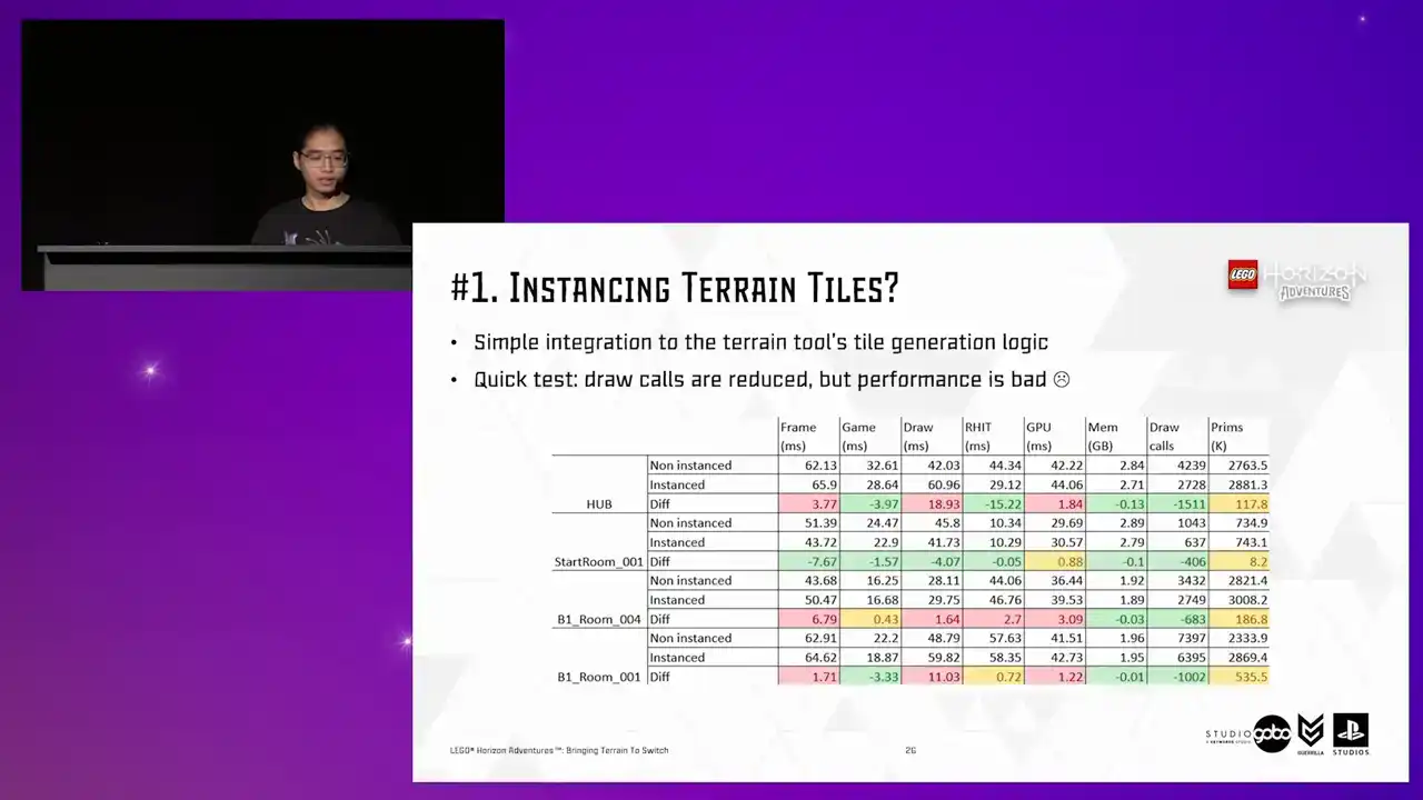
But unfortunately, a quick test showed this is not the case.
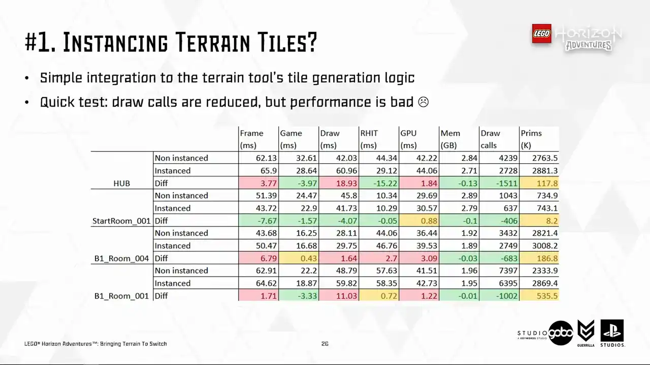
The performance is even worse than the non-instance versions in many cases. With the render thread cost, particularly high in some level, for example, the hub level on the top have a stonking 19 milliseconds increase.
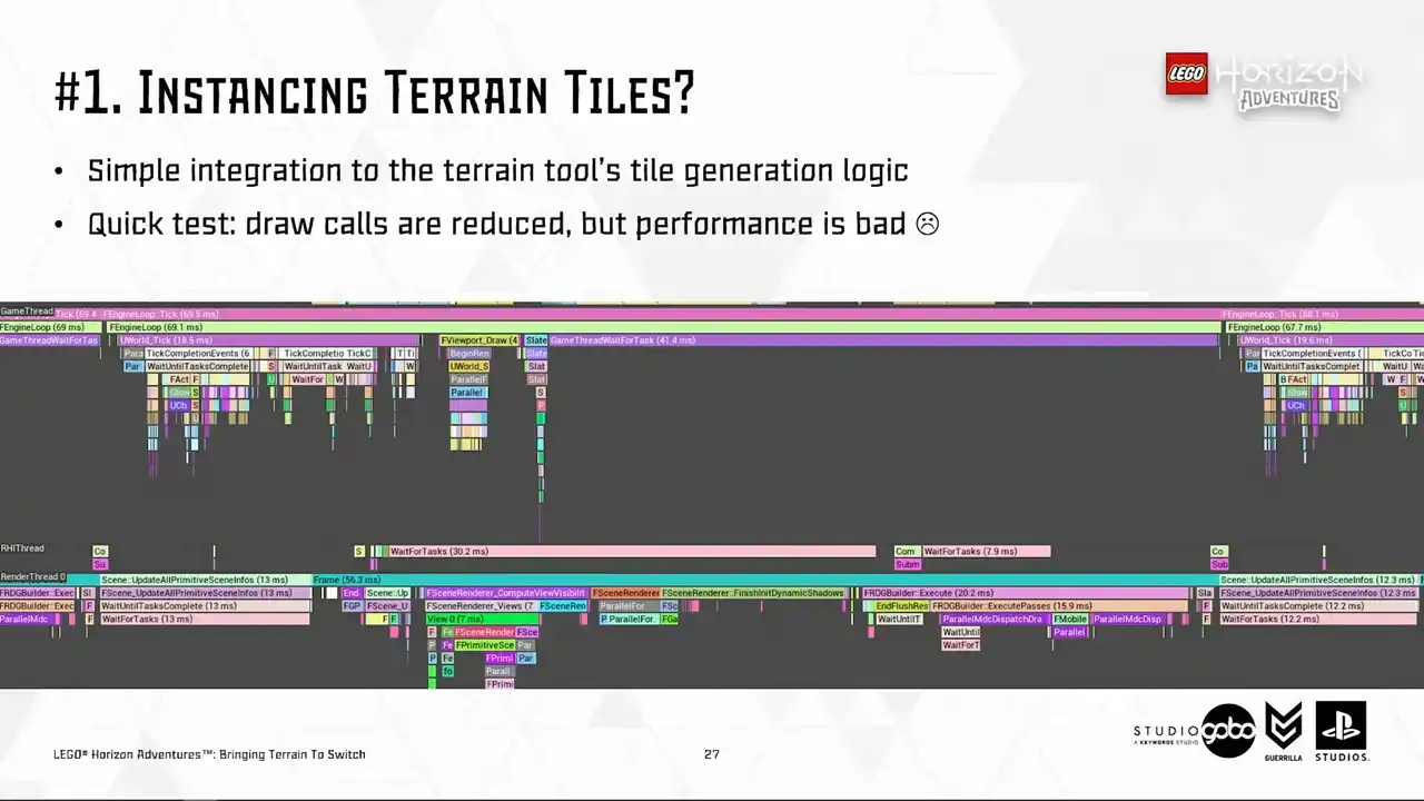
So looking a bit more closely, the render thread new bottlenecks are mostly caused by HSM, from the view visibility work to the dynamic shadow work. So that is one part of the problem, the CPU side. How about the GPU side?
Well, the GPU side is also suffering as well, probably related to the higher primitive count.
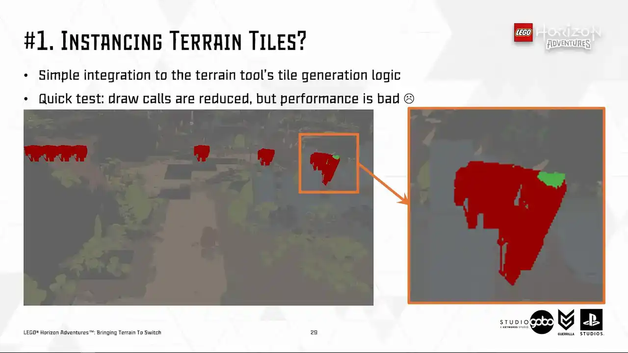
because sometimes the entire instance cluster is rendered despite only having a few pixels and are being visible.
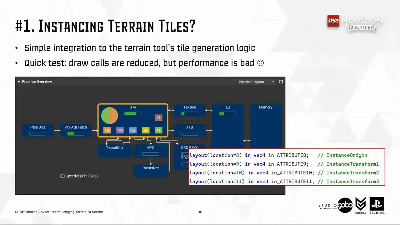
And in addition, HSM has a few extra vertex attributes like you see here. So it costs more stores fetching all these vertex attributes into GPU.
The background information is that vertex cost is a big problem for us in this project and multiple teams have chipped in to solve this. For example, TechArt helped bringing mesh complexity down while the rendering team employed some optimizations such as 16-bit floating point vertex position. So anything that causes more stress on the memory bandwidth side of things
is not going to fly because essentially it's just undo all that other optimization.
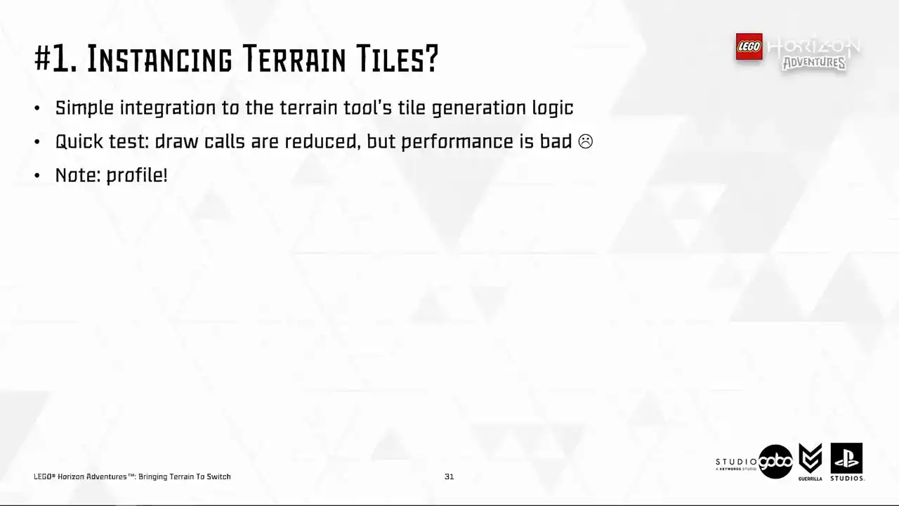
So sadly, we had to park this direction, but your mileage may vary because I heard that there were a lot of improvements on how the engine handles instancing since 5.3. So make sure to profile in your case.
Perhaps your vertex processing cost is not as high as ours, so the cost for extra attributes is not even a concern. So the second idea we had is to generate a unique Lego model per terrain patch. However,
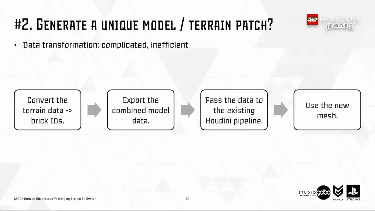
it would involve somewhat a complicated data transformation process, as you can see here, and that is not very efficient. But more importantly, the sheer number of assets being added is what's going to put us off. So to demonstrate, we have around 150 levels containing the terrain with number of terrain patches per level around a few dozens. This means we will have thousands of LEGO models, each of them very complicated as they are merged together from simpler models.
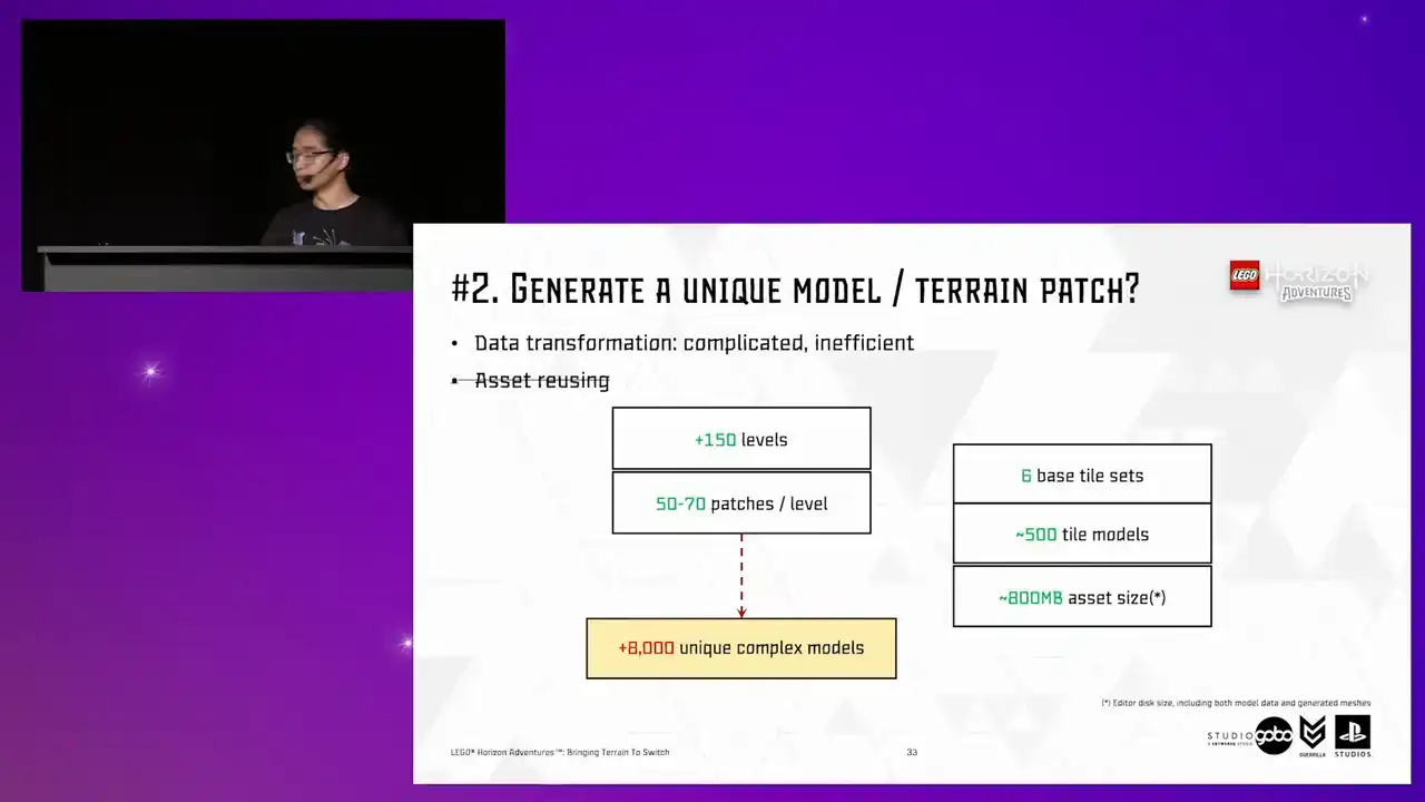
To compare, we have around 500 tile models across all tilesets we have in the entire project.
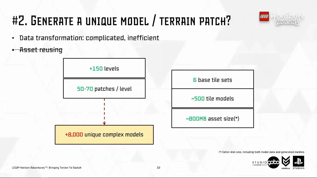
So all of these already cost us around 800 megabytes for the asset size in editor. So the prospect of having thousands of extra terrain models looks very scary.
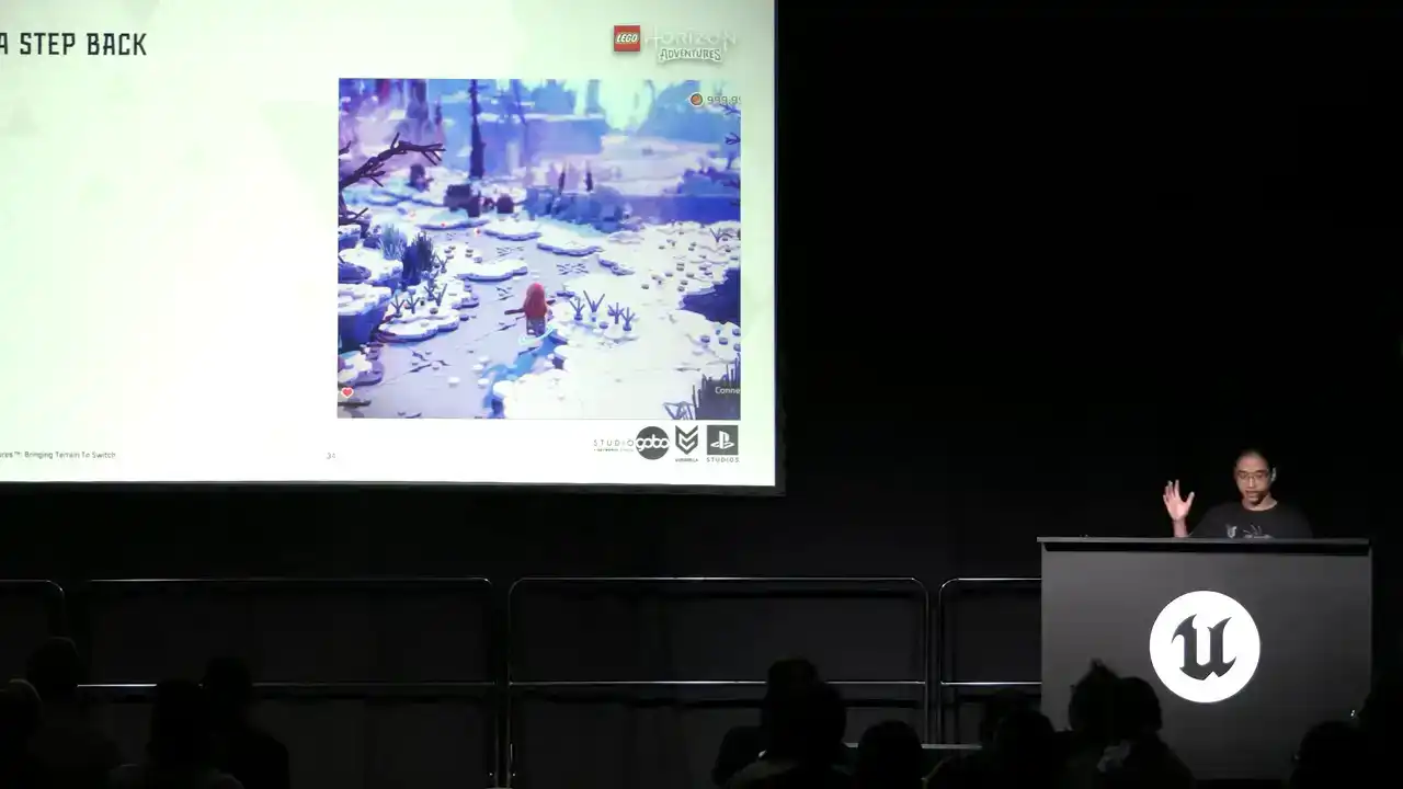
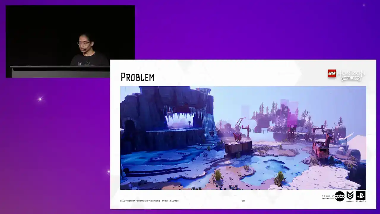
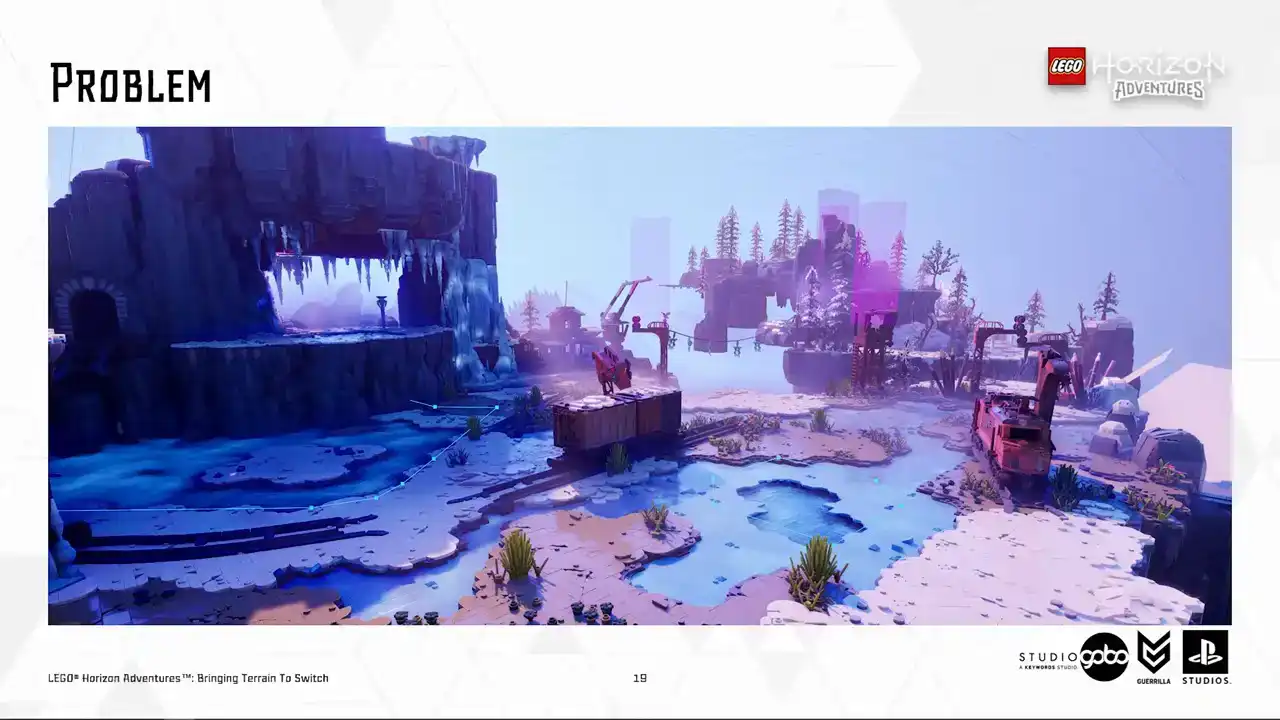
So at this point, we took a step back and look at our scene.
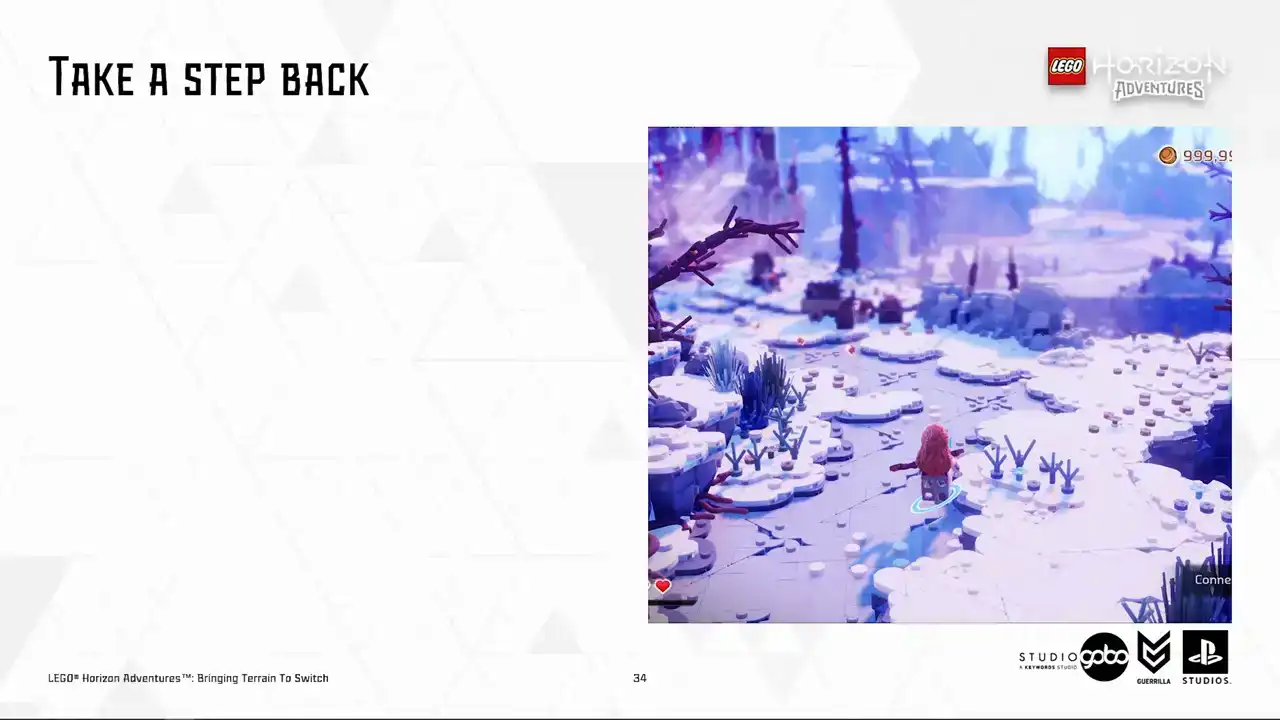
So here is an example scene I have. Having the close by terrain patches rendering in
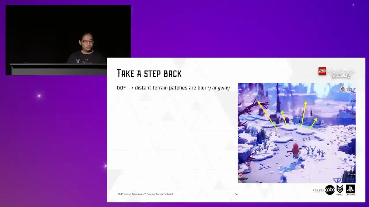
high detail is not an issue for us, but it is more of an issue for distant patches. and with the help of depth of field, they are going to be blurry anyway.
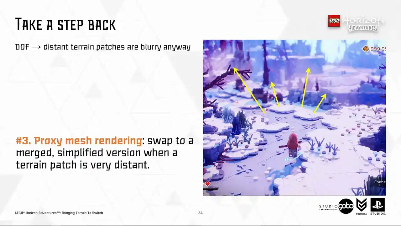
So we set out to explore the third idea, which we call proxy mesh. The idea is similar to the H-Law system in Unreal's world partition, in the sense that faraway patches are swapped to a merged and simplified version.
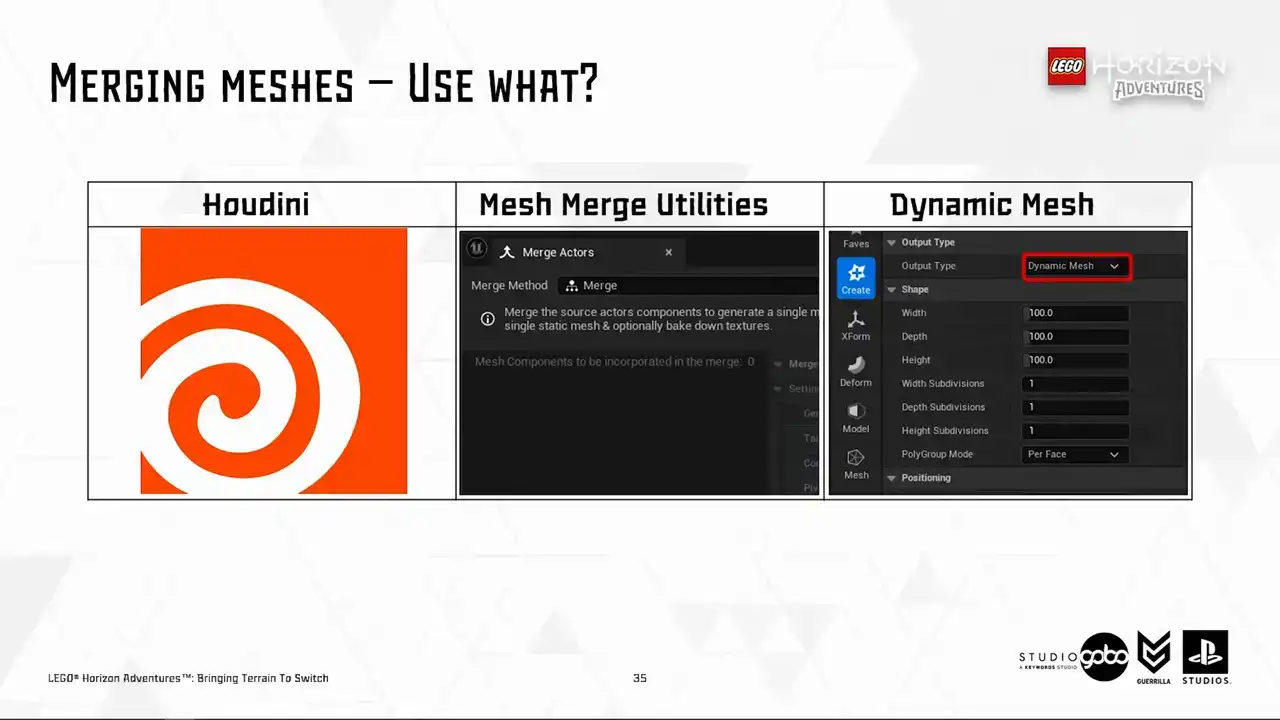
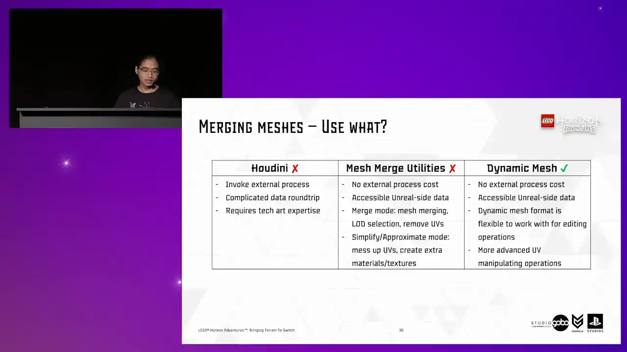
So to do this, the first part of the puzzle is obviously how to merge these meshes together. Here are a few options available for us. So Houdini probably needs no introduction. But for other two, in case you don't know, Mesh Merge Utilities is the logic toolkit behind the engine's built-in active merging tool,
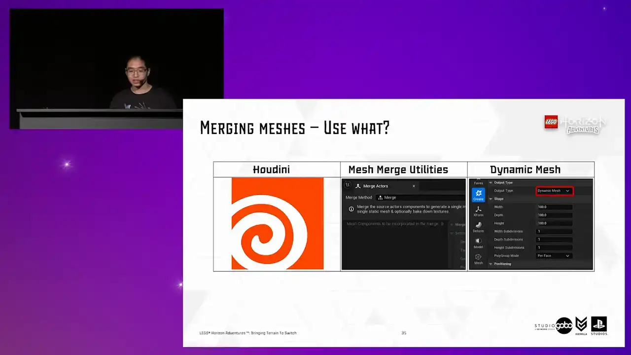
while Dynamic Mesh powers many in-engine mesh editing operations from the modeling tool to the ability to manipulate geometry using scripting like blueprint of Python. So long story short, we ended up choosing to work with the dynamic mesh format.
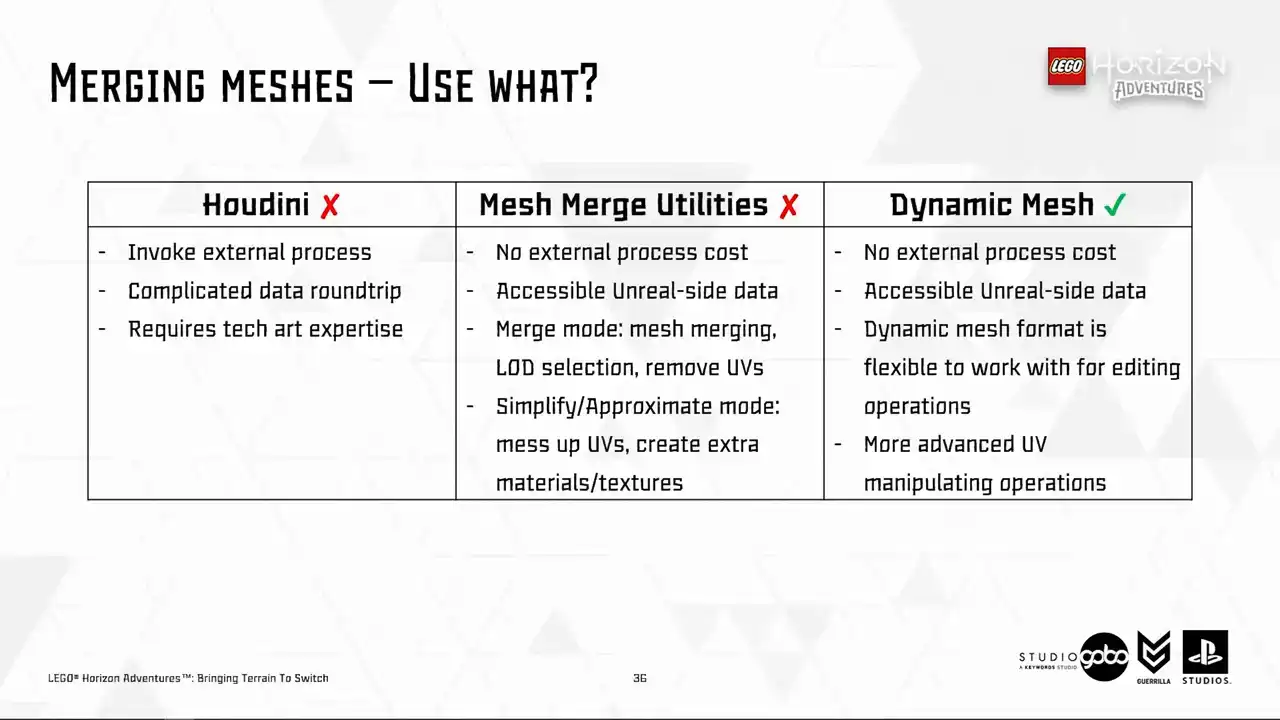
It stands out for this use case because it provides some sorts of balancing because it provides more flexibility than mesh-merge utilities, but it doesn't require invoking an external process or requiring any sort of data round trip like Houdini. So I prepared a few snippets to demonstrate it in action.
So let's see how it goes. Cool, so here is the first snippet.
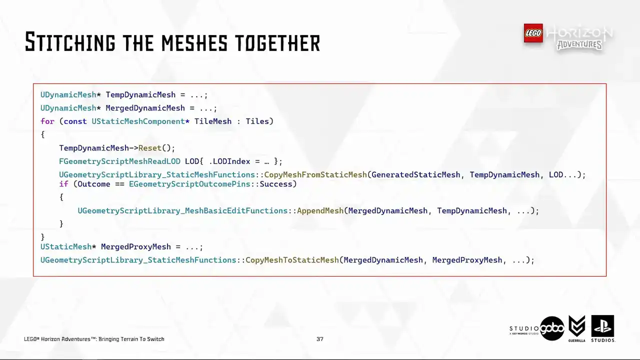
I added for merging the individual tiles together. It's very simple because like I said, there are many built-in engine operations that works with the dynamic mesh format, including a few geometry script helper functions that you see here. All this snippet does is to take the individual static meshes, copy it to a dynamic mesh. You can also choose the load of the source mesh to copy over to the dynamic mesh as well. Then I just append the current tile mesh to a merge mesh, which later gets copied to a static mesh asset when finished. So at this point, it's ready to use in engine.
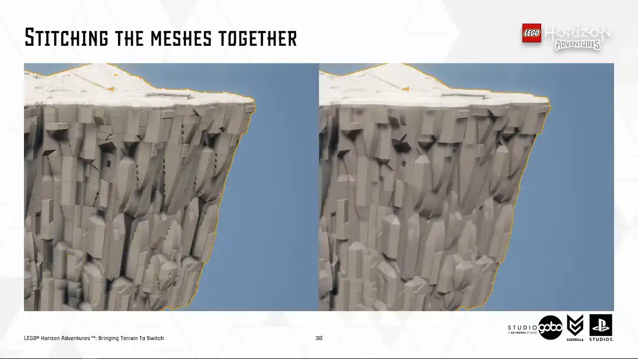
And yay, this is what we have, the first part of the puzzle solved. I'm using lot zero to demonstrate the idea, but in reality, we use the highest possible lot to reduce polycount.
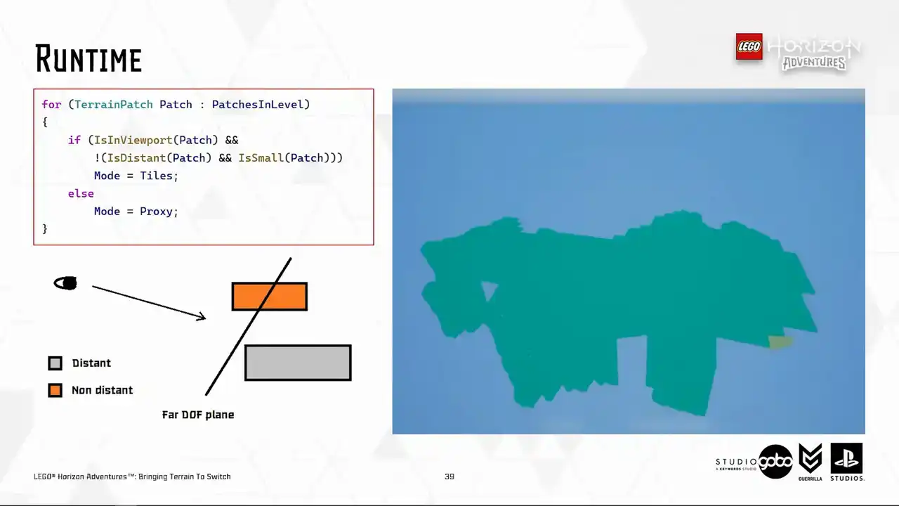
So the second part of the puzzle is to actually display the merged mesh at runtime. and use a very simple algorithm based on the balding box of the terrain patch to determine if the size is below a certain threshold, it's going to be small. If all the vertices of the balding box is behind a far depth of field plane,
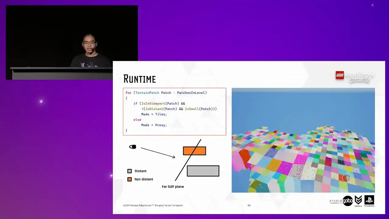
an imaginary plane like the image in the bottom left, it would be considered distant as well. So if a patch is either outside of the viewport completely or either distant and small, we will show it in proxy mode. So by showing in proxy mode, I just mean that hiding all the individual tiles and showing the mesh mesh and vice versa. So this allows us to whip up a very quick prototype to test out the number on device with a constant depth of field distance. So this is a test level where I get all the Turin patches in our hub level, which is the most complicated level in the project in terms of terrain, or in general, sorry.
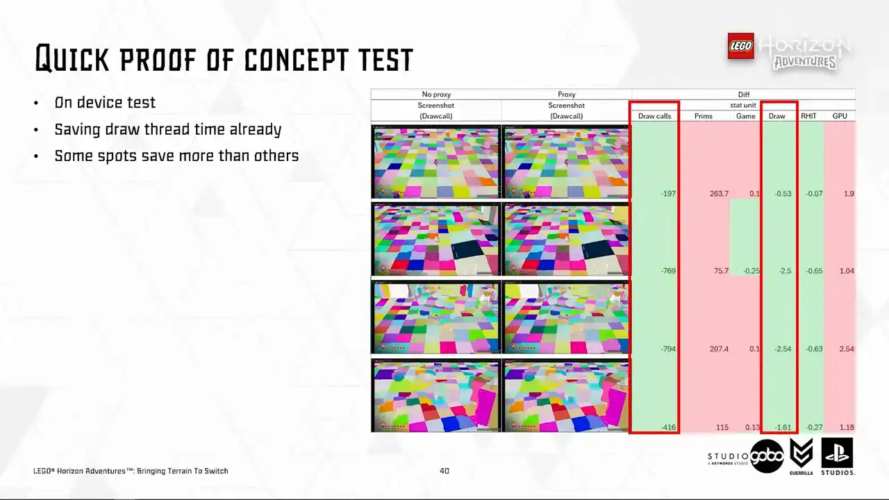
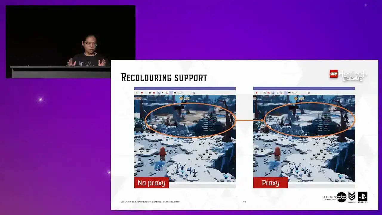
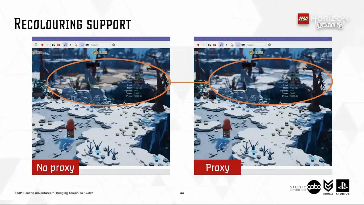
We can see that the draw thread cost is already coming down, ranging anywhere from 0.5 to 2.5 milliseconds, depending on where the character stands, of course. But it does kick up GPU time and triangle count, but that is expected, and we have some ideas to improve. So the first idea is that as a patch can get quite big, but just a fraction of it being visible in the viewport.

So sending a big mesh over is kind of wasteful. So the issue here is similar to the instancing cluster problem that we faced earlier,
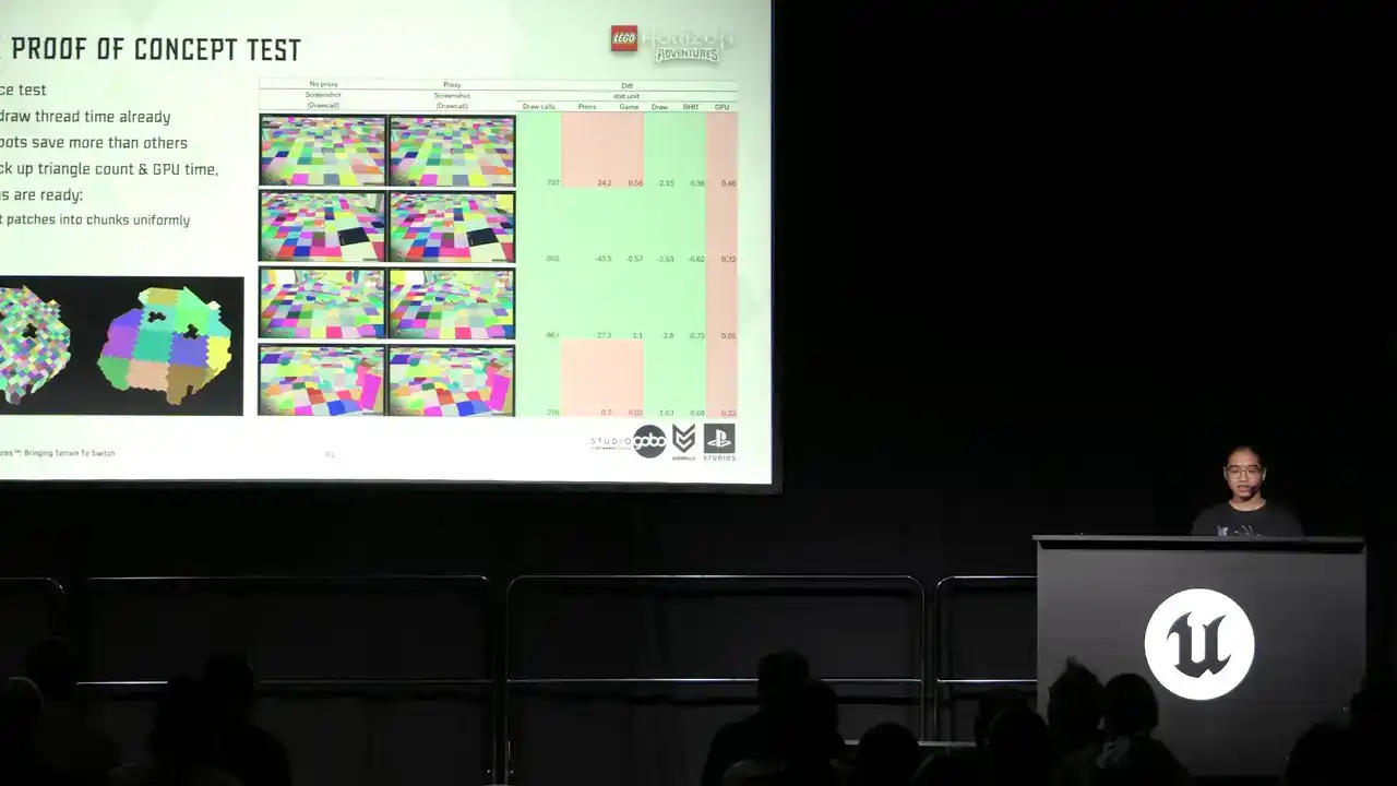
because CPU side cooling cannot reliably decide if this mesh is worth sending over to the GPU to render. So we can aid this process by splitting the patches into smaller chunks.
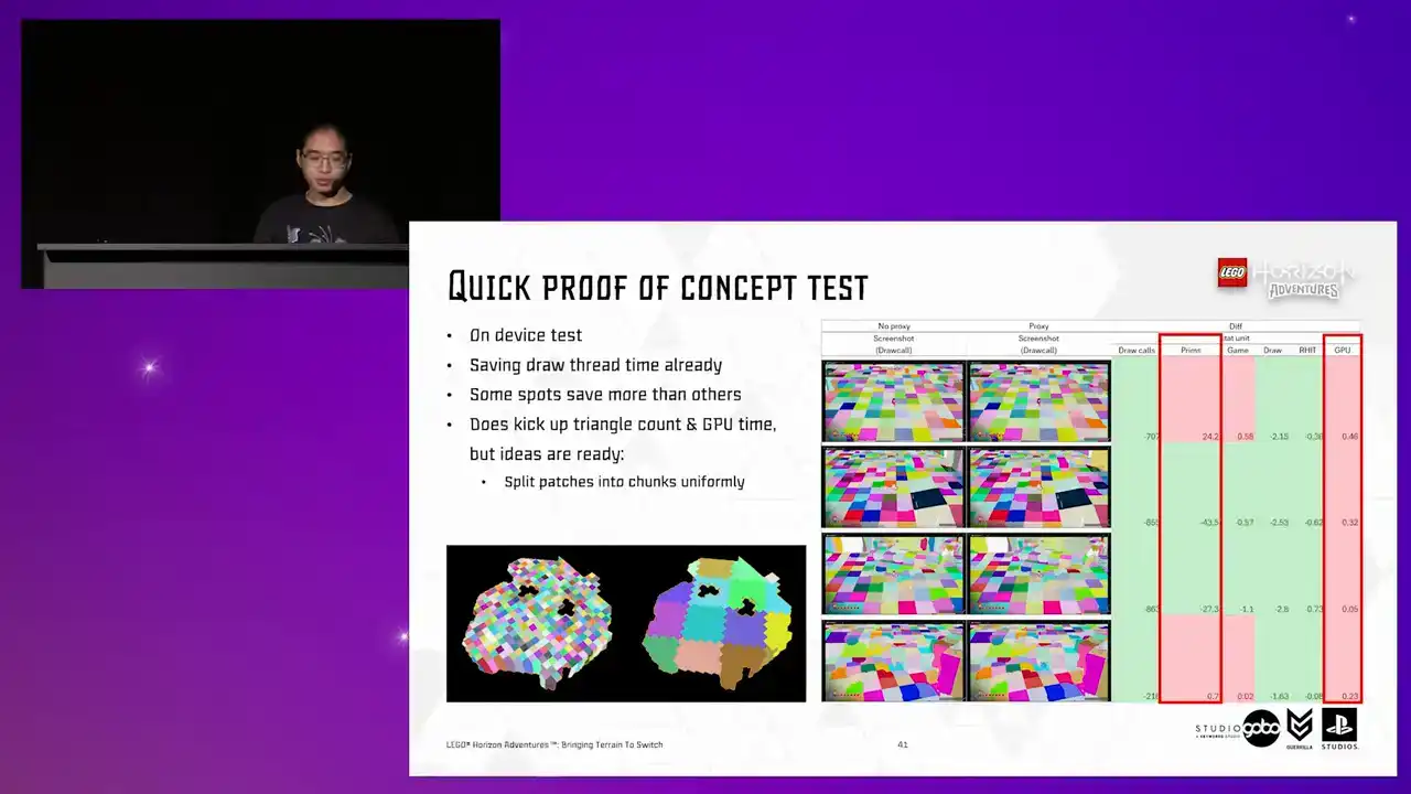
So doing this alone already helps bringing the polycount and GPU time down closer to the base level. So if you look into the primitive count,
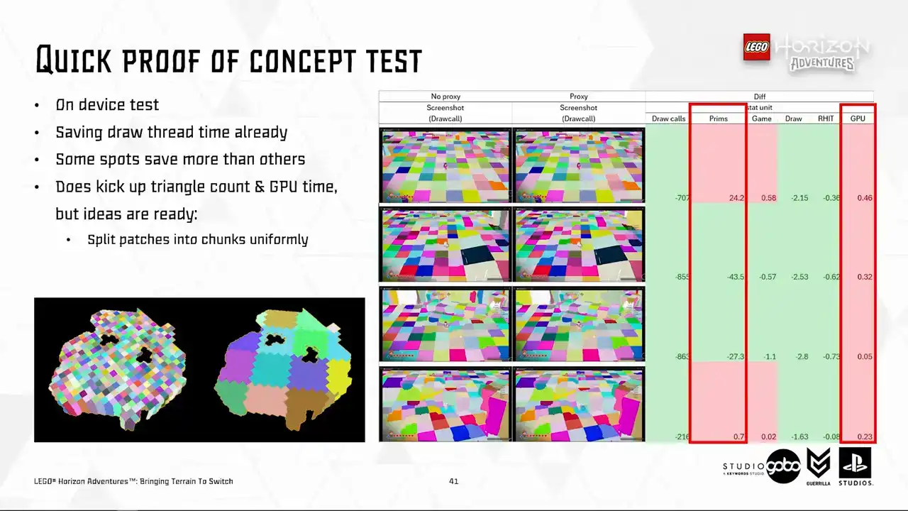
it's very close to the base level as well. and with TechArt releasing more optimized version of the Heiger Lords, the poly count will be brought out even further as well. So this is not something we're too worried about.
Okay, now we are content with the performance characteristics of this direction.
We can start to think about how we can rule this out without affecting the artist workflow. So with what we have so far, it's quite easy to employ the auto-regenerate unsafe mechanism, similar to how Unreal's HLOD handles its proxy meshes. And to avoid generating everything in a level unsafe, which can take a while and more scary, piss off the artists, we store the checksum of the terrain patches to quickly determine those that were changed during the edit.
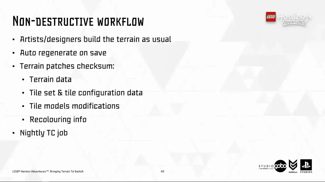
We also have a nightly Team City job that does a scan through all the levels of the game and update the terrain patches in these levels as needed Occasionally we still need to manually trigger the job
where these proxy meshes can be forced regenerated. For instance, if we want to do some breaking changes in the code or in any of the data. But that is something we do overnight

and we can live with this inconvenience every once in a while.

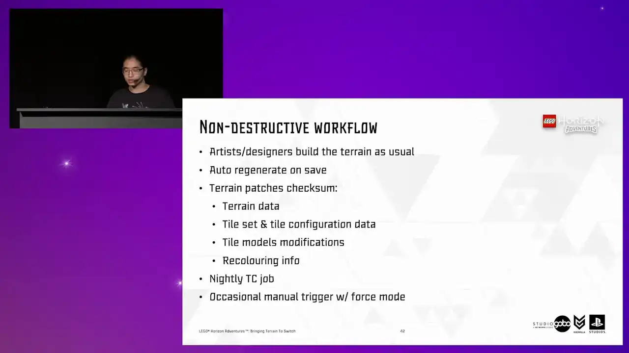
Then we want to be a bit more mindful about the asset size. To do this, we did several things. The haggist lot, as I mentioned several slides ago,

has been very optimized at this stage, thanks to the work our techout team put in. But once the mesh is merged, there's always extra room for further reduction settings.

Unused UV channels are stripped out as well. I will touch on this in a minute, but in the meantime, let's see other options. We can strip out ray tracing acceleration structure for the generated mesh as well, because it's not like we are doing any fancy real-time ray tracing on switch. Next up, navigation and collision is not needed either because these meshes are only displayed
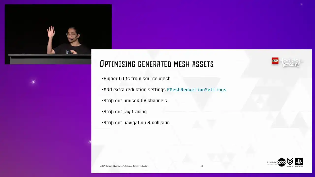
at a very far distance and the character does not stand on them and furthermore the original tiles with navigation and collision enabled is still there, they're just hidden. And also earlier in the project we made a decision not to use the mesh distance field on switch as well. If I recall correctly, it was adding like 2.5 milliseconds for the base pass or
something like that. So that goes as well. The thing to take away from this is the last four items are turned on by default. So this can be easily missed and take a lot of space unnecessarily in our cartridge.
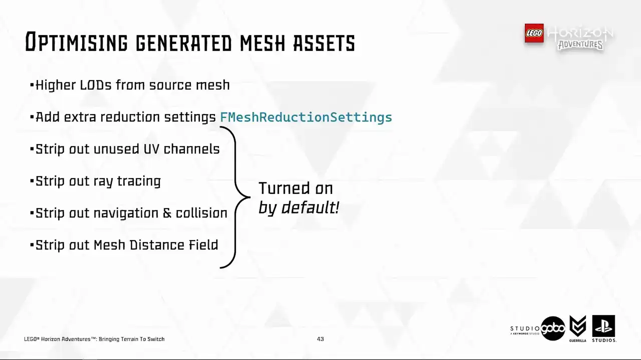
So this is something probably worth looking out for. So all of these save like 90% of the asset size, for example, all the proxy meshes in the hub went from 100 megabytes to 8 megabytes.
Okay, so with all of this, we can be more confident in the idea and can start tying up loose knots in terms of quality and correctness.
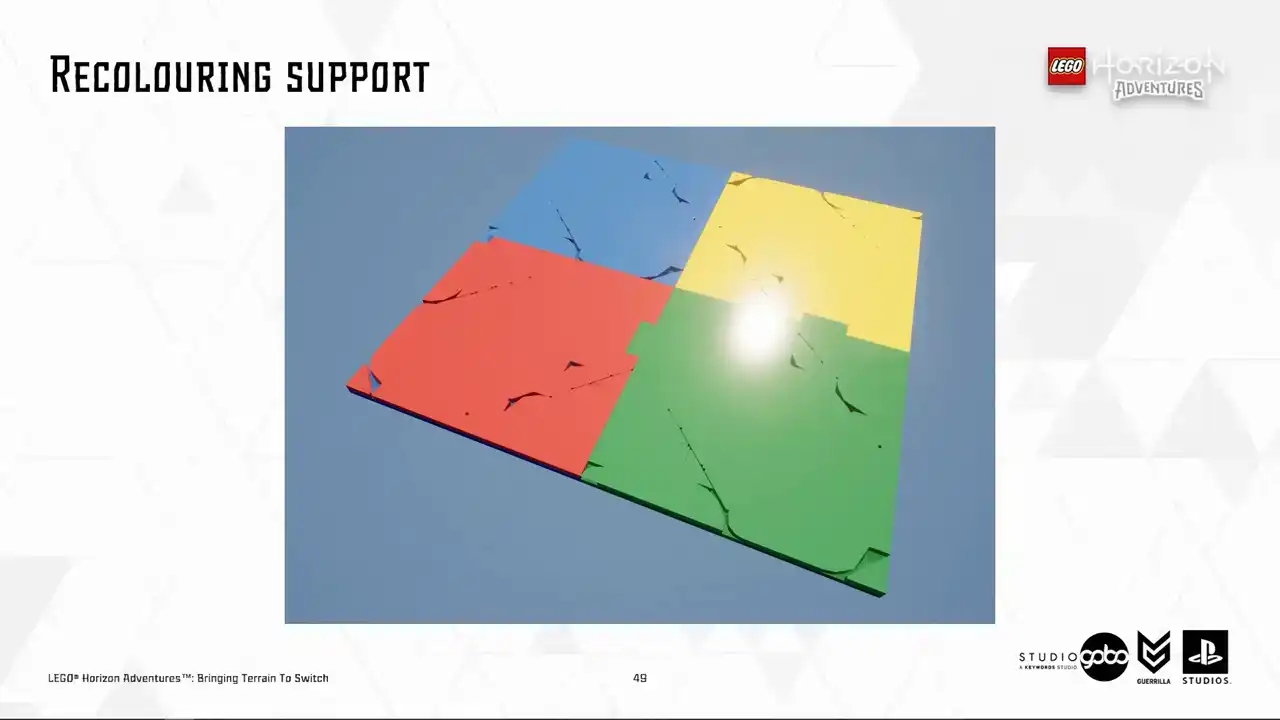
So I hope that you still remember our recoloring feature because the first issue we noticed is the correctness of the recolored Turin patches as highlighted here.
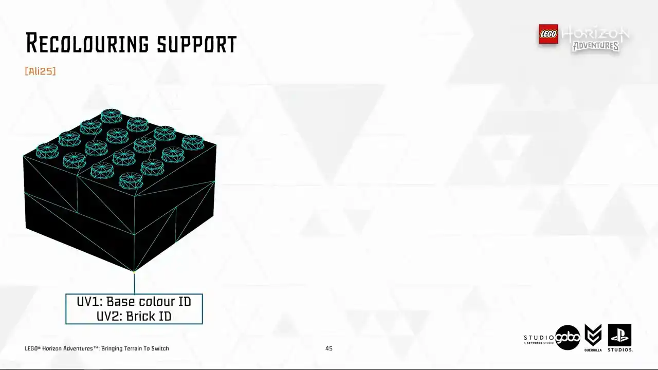
So now the time for a super quick explanation of how recoloring works. So to start with, the Houdini mesh pipeline stores the Lego color ID in UV channel 1 and brick ID in UV channel 2 of the vertex.
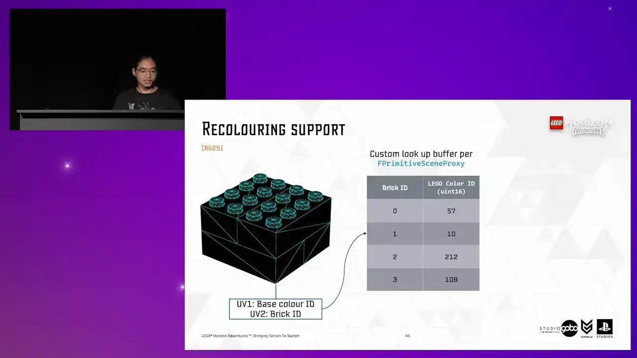
If a model is recolored, its scene proxy has a lookup buffer specifying which color does the brick has eventually. Then the color ID, either from UV1 as a base color
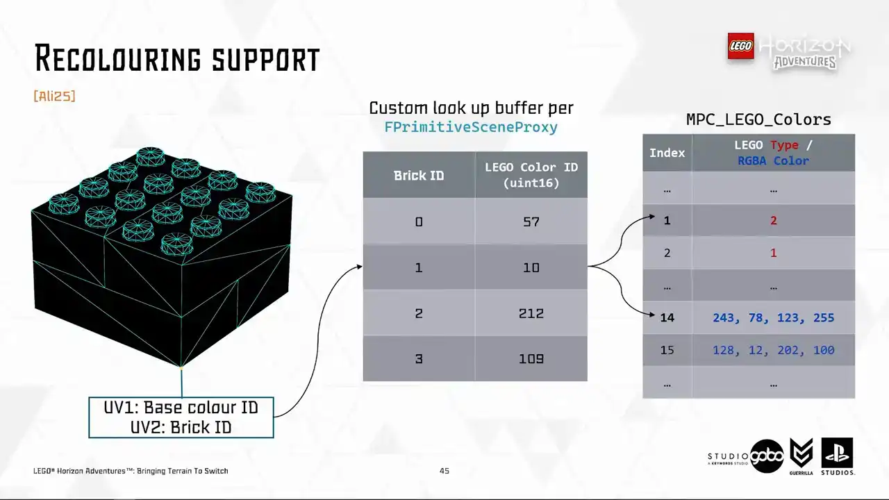
or looked up from the recoloring buffer, is then used to look up the actual RGB value in a material parameter collection. So for proxy meshes, we don't want any of these dynamic lookup. We will just write everything down to UV1 and we can reuse the existing material.
Aside from cheaper runtime rendering cost, we can reduce memory footprint and package size by removing UV2 as well. So this is the remove unused UV thing that I mentioned a few slides ago,
among other stuff. So here is a test I'm going to use. It's like the worst case scenario test
because for terrain our artists mostly use bucket coloring instead of painting them into arbitrary color strips like this. So if this test case passes we should be good in production.
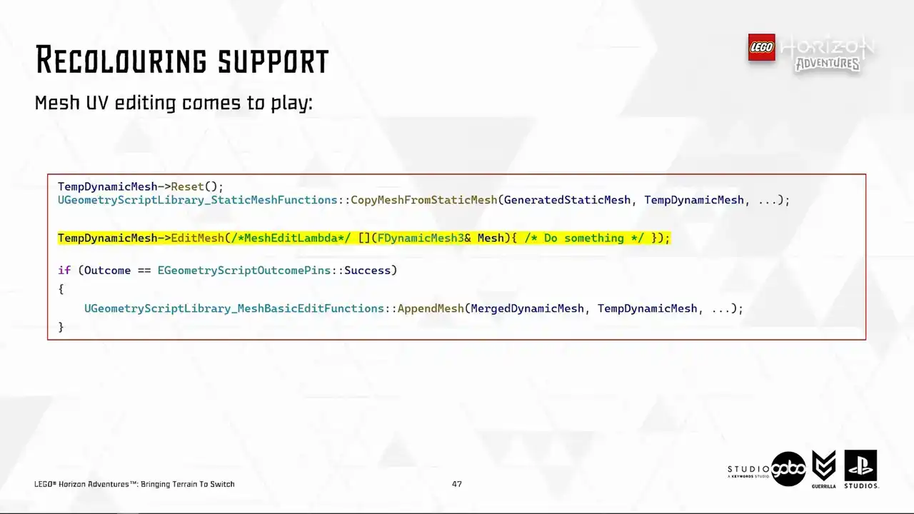
So circling back to our mesh merging code, so far dynamic mesh does not standing out comparing to simple utilities like the mesh merge, but now it starts to do so by providing
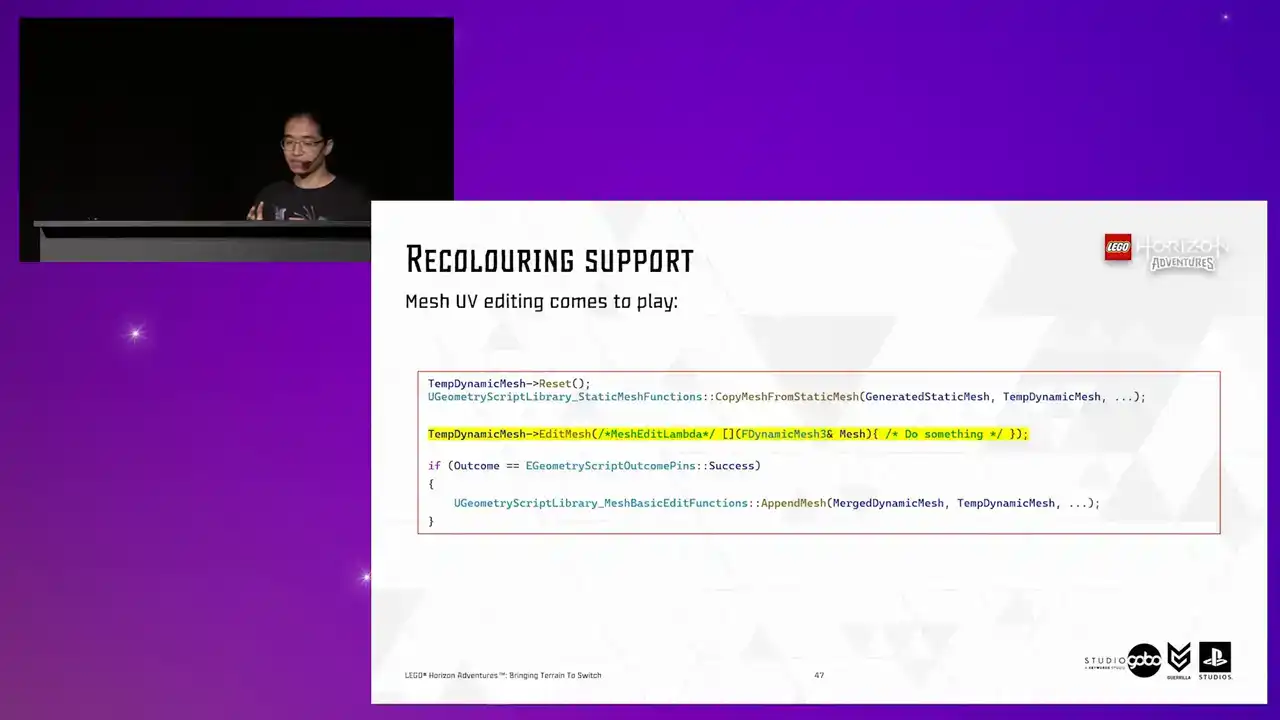
the mesh editing mechanism. The edit mesh function is quite flexible or it requires it's just a lambda to define what do you want to do with the mesh. So here's how the lambda being passed to the edit mesh looks like.
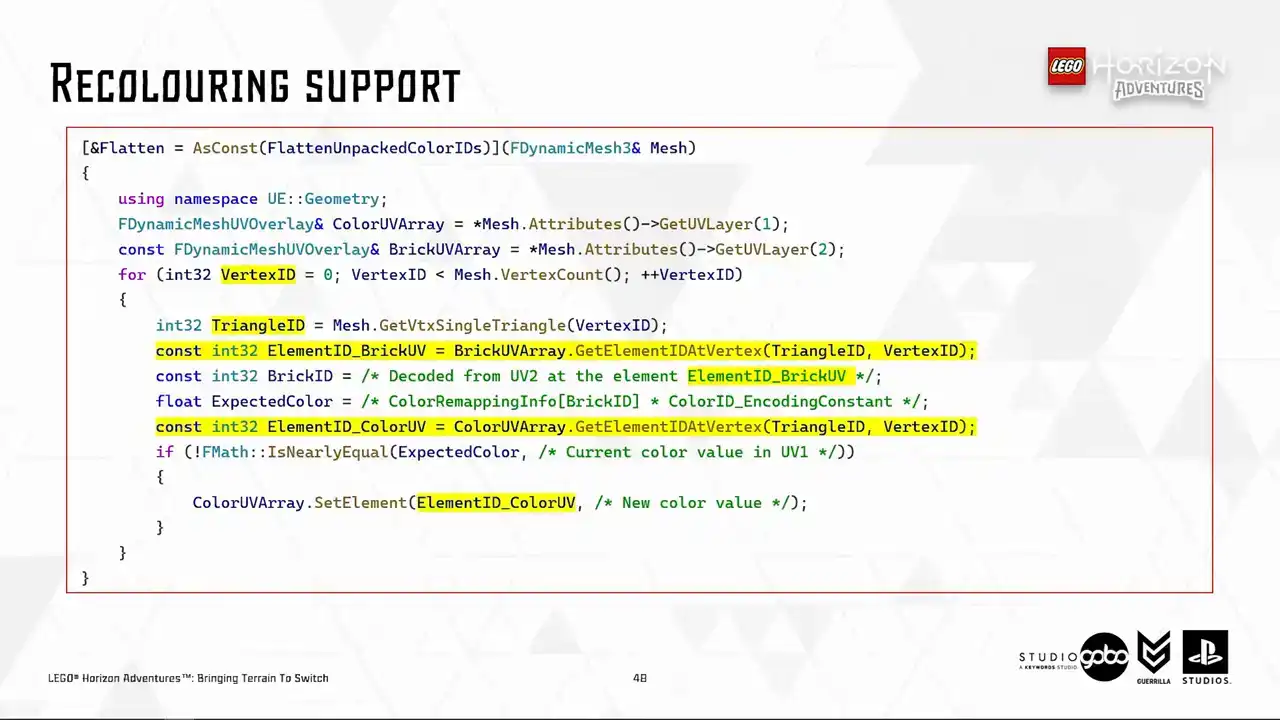
The logic is what we discussed before. We just fetch the expected color value using BrickID from UV2 and then the recoloring buffer and then write the value down to UV1 So with a very few simple function calls we can manipulate the mesh in engine
So we are just touching, like scratching the surface in here.
The dynamic mesh is a very powerful format, which the potential is very large. So one little tip here is to make sure to access the elements via the persistent vertex and triangle IDs. The reason is that the vertex, the same vertex may end up in different element ID in different UV layers. So if you assume the same element ID
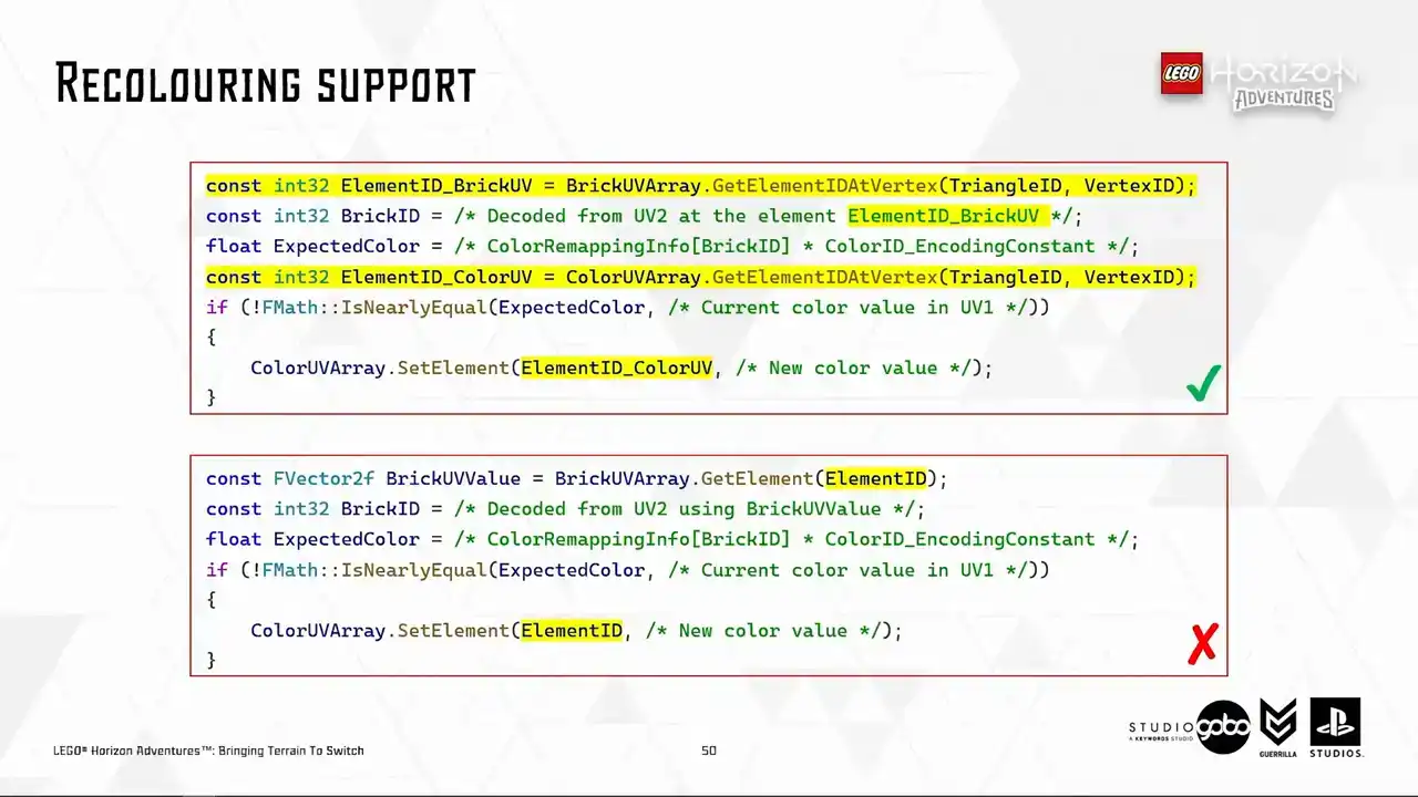
across different UV layers pointing to the same vertex, the result will be wrong because I found out about this the hard way by actually making the mistakes.
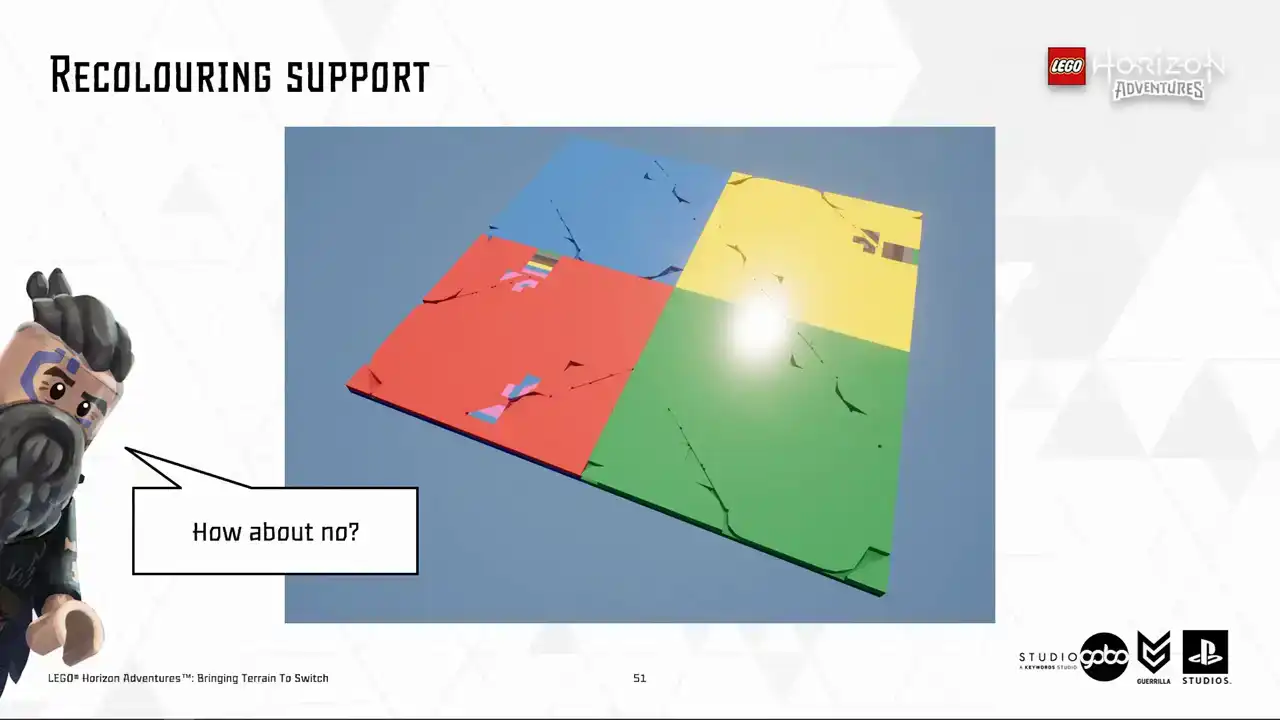
So this is how the mistake looks like. The final vertex color gets written to the wrong element causing V a triangle to show up in the final mesh.
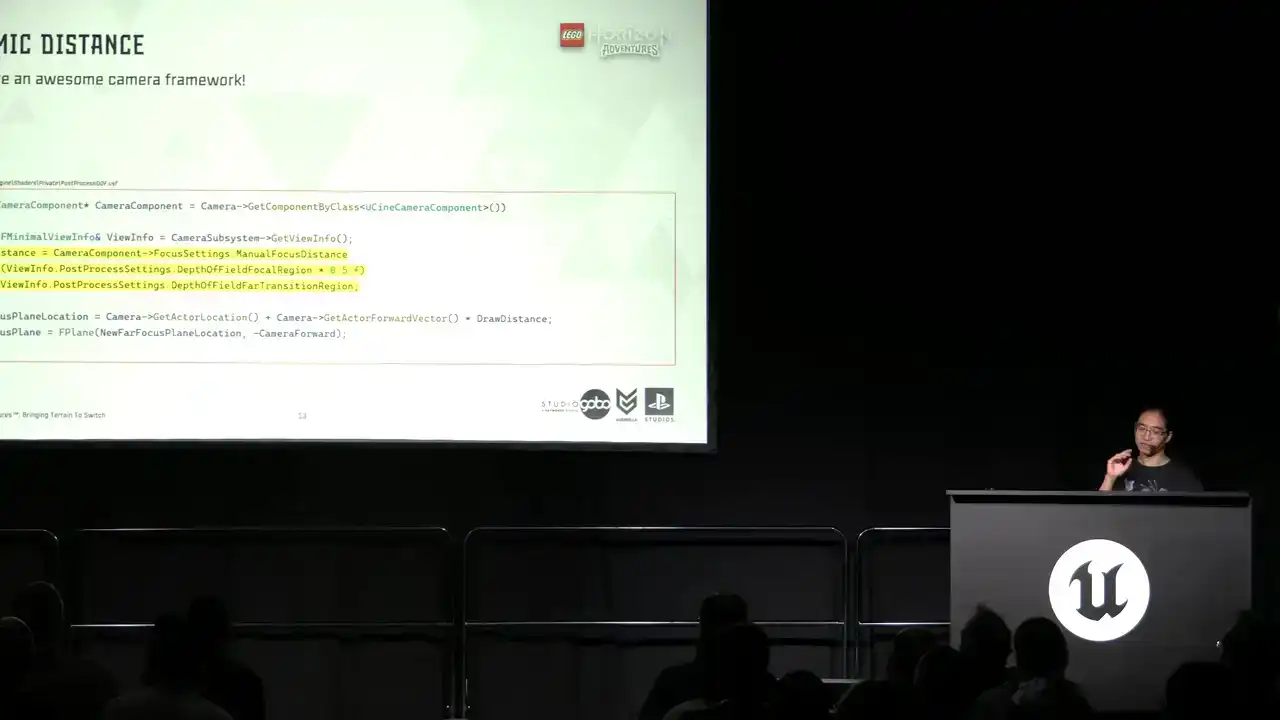
So the next improvement we made is a dynamic draw distance because so far what we have is a constant DOF distance.

So this aims to utilize our awesome camera framework. It's dynamic because many things can influence the camera such as player one and two in co-op mode or interesting points on the map or entities in combat.
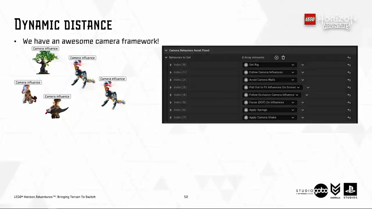
It is also very customizable because the designers have lots of tweaks to showcase the world.
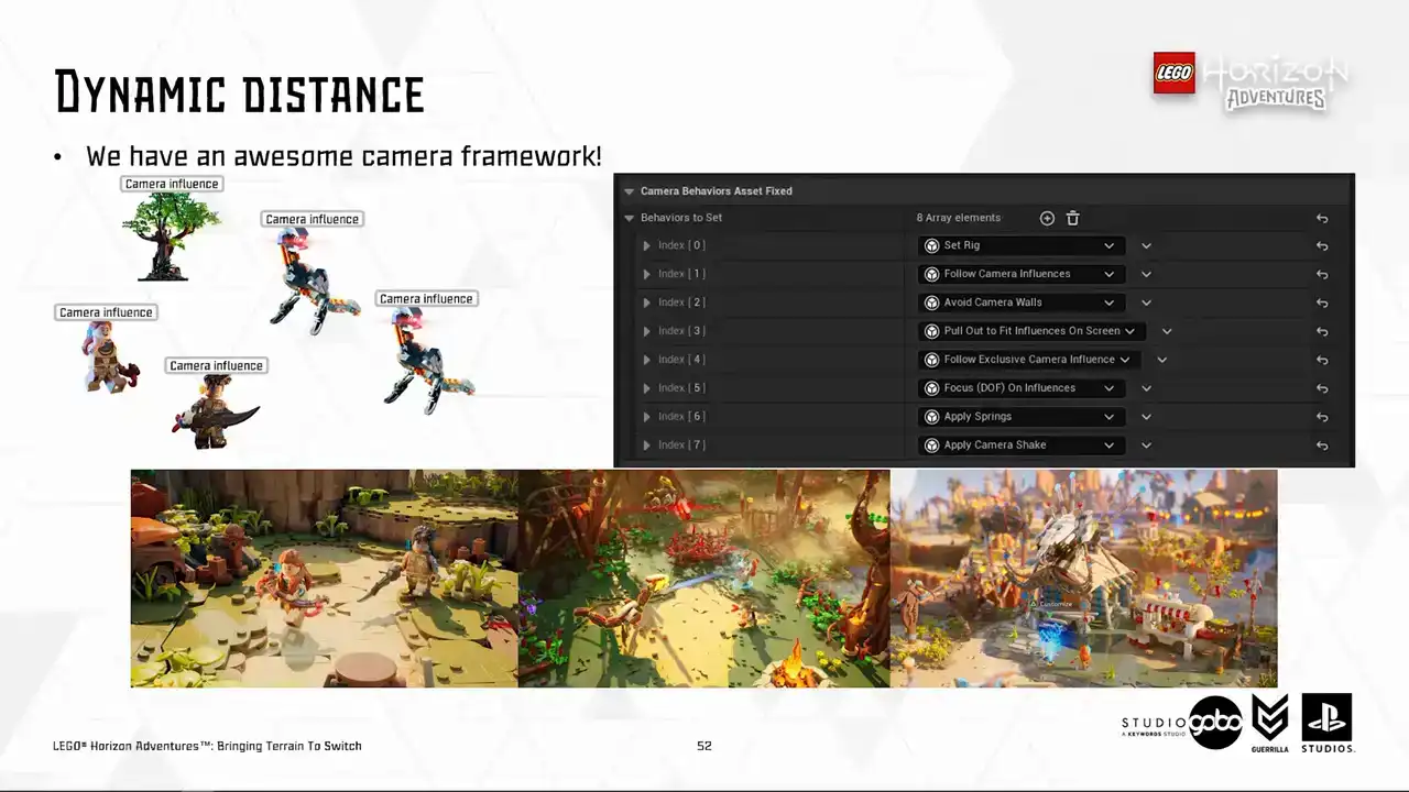
And lastly, it covers a very large range of context from usual map discovering to combat to boss fights and cinematics and etc.
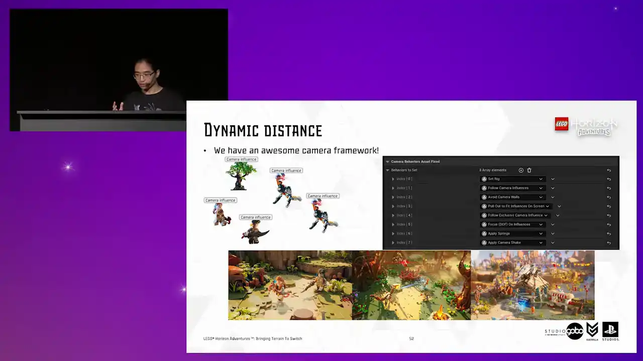
So it's very thorough.
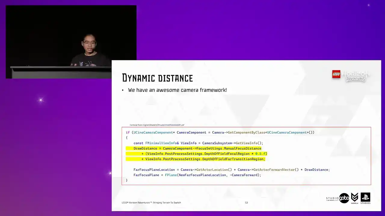
So we need a dynamic distance. so it turns out to be easier than I thought
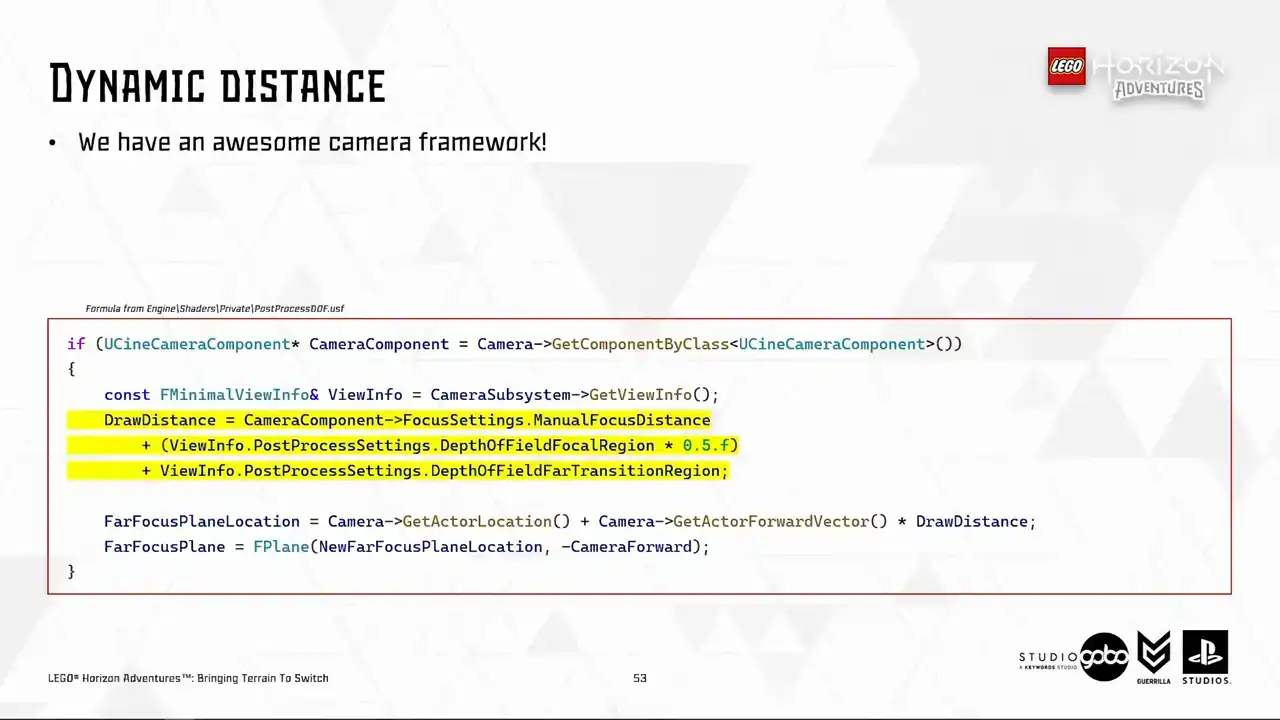
because everything eventually gets based down to the built-in scenic camera component which already has all kinds of info so I hijacked this formula in the DOF post-process shader and then I whack in a kind of buffer distance in there just to be sure that the DOF distance is far enough to avoid any noticeable popping and we're ready to go that buffer distance is totally optional
you can have that or not
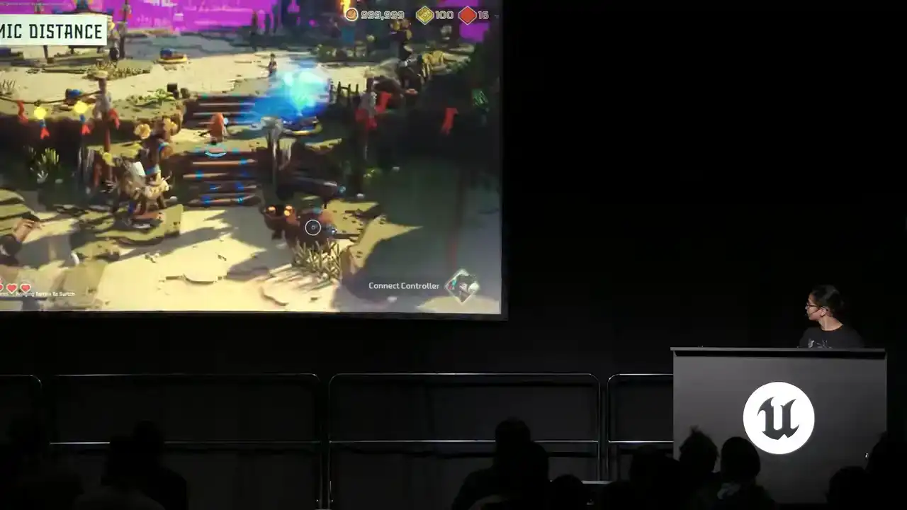
So here's the dynamic draw in action.
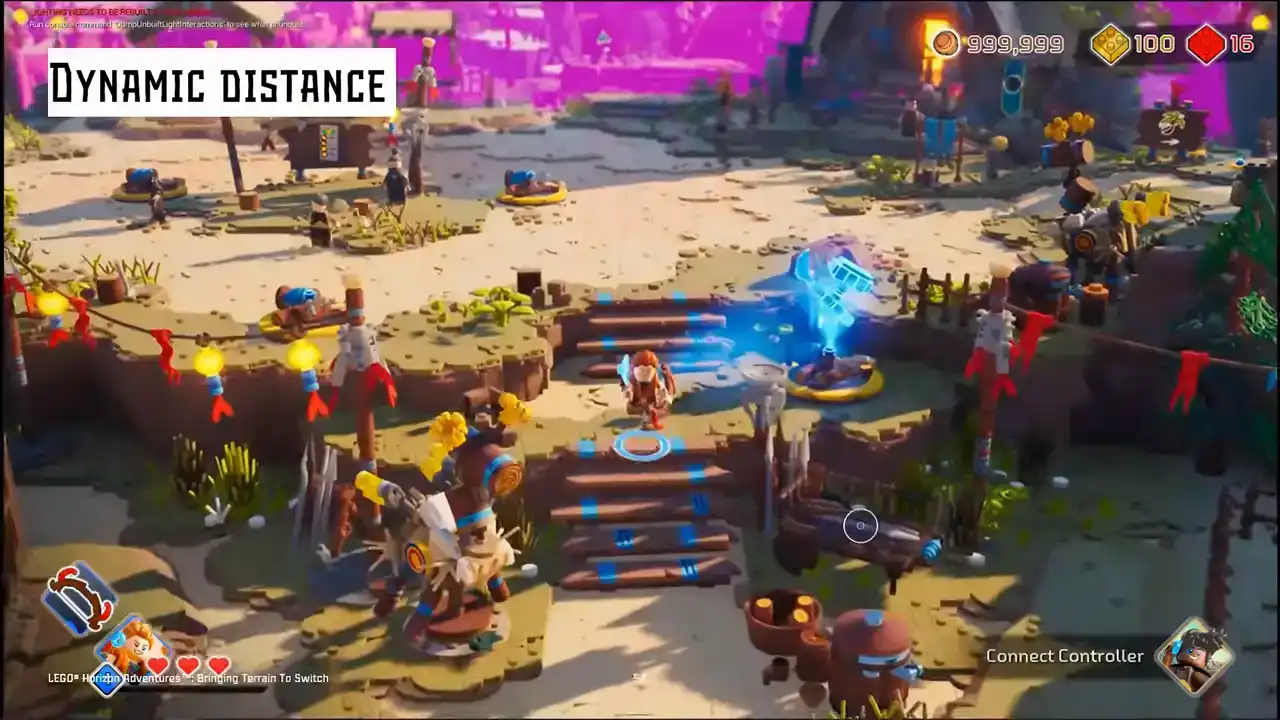
You can see that the purple plane does move around
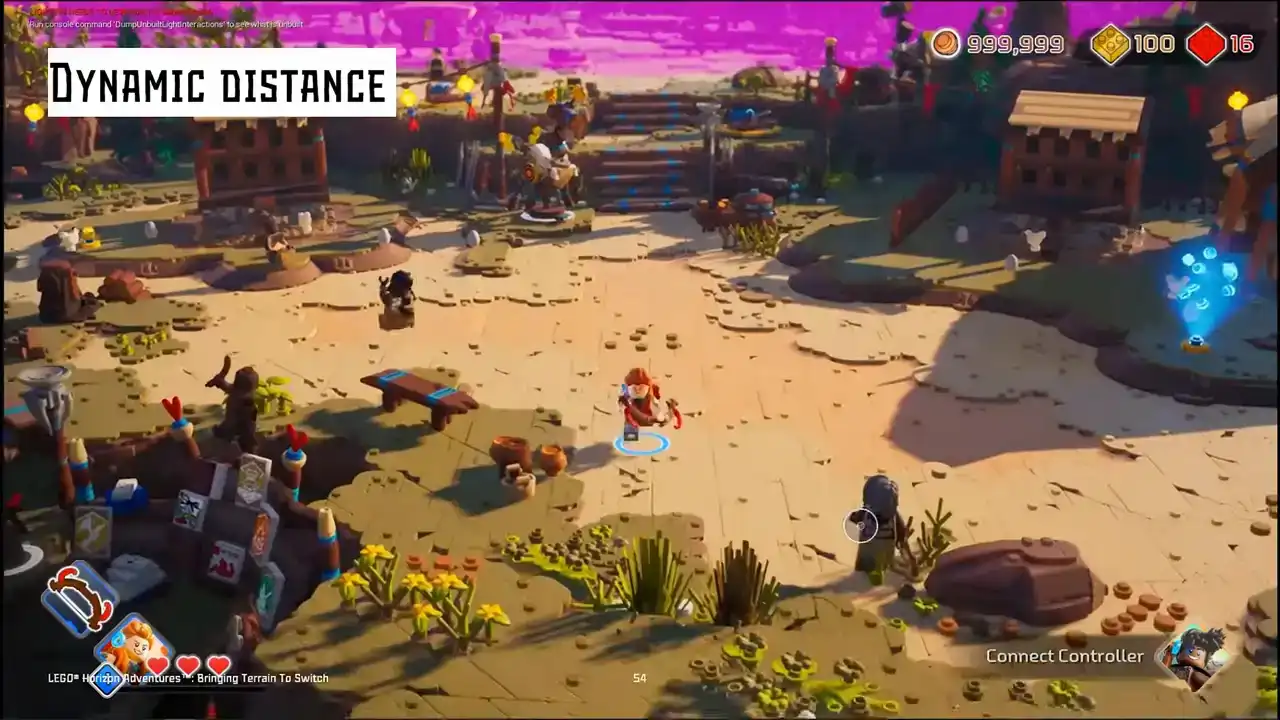
in different camera situations
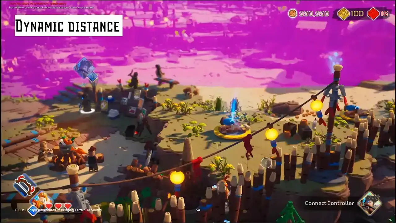
based on the camera settings in each frame.
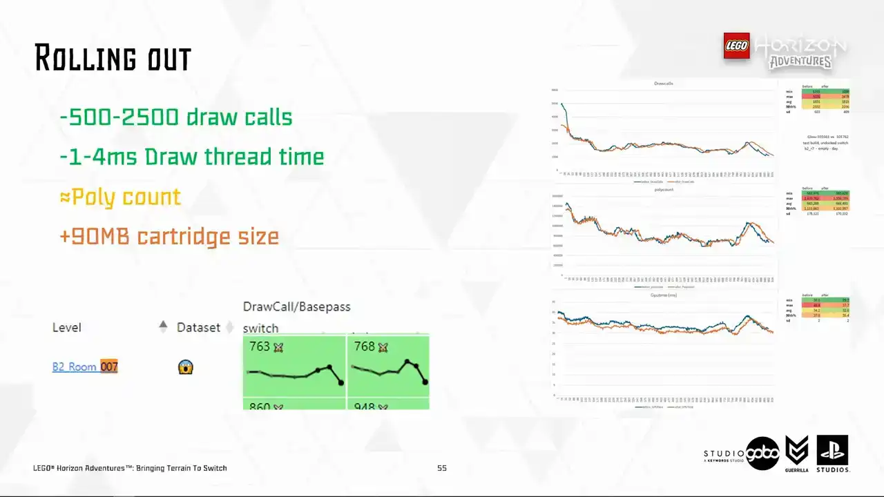
We're nearly there. We started rolling this takeout to several levels as a final step test, step test starting with levels like the hub or a few most raw core bound levels in the project according to our performance dashboard. We were very happy to see the relevant performance metric starts to pick up overnight. Then the promising signs
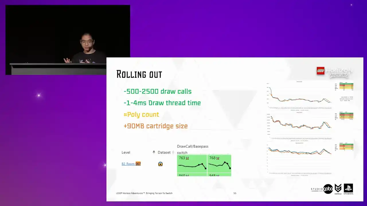
are there. It's just a matter of rolling it out for other levels for more win across the board. So in the end it added about 90 megabytes for all generated terrain proxy meshes in the project. which is still acceptable given the improvement in runtime that it brings.

Okay, so before we close off, I want to introduce a fun problem. We observed that for some levels, the Turing proxy runtime code, which toggle the proxy meshes on and off, causes end of frame hitches.
this is reproducible for dense areas with lots of static mesh component being set visible and visible at any time. So turns out set visibility is not exactly free.
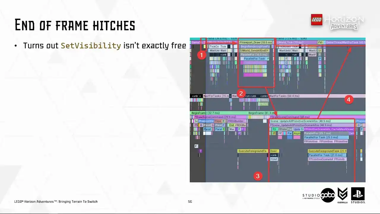
So allow me to explain what happens here. So number one is where the terrain system issuing set visibility calls. These calls are not processed individually, but the game thread will send them into the render thread in a batch, as you can see in number two at the end of the frame. In number three is the render thread actually process these requests.
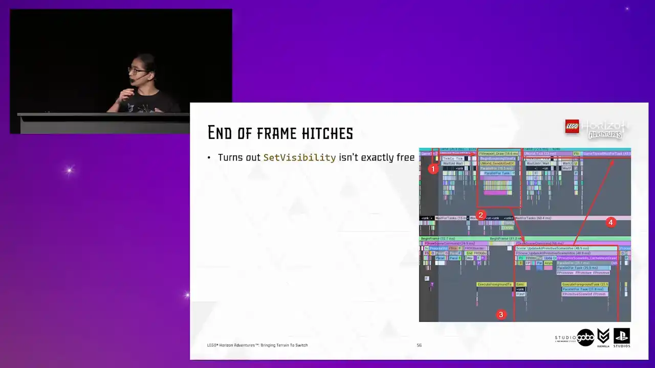
So it does it by firstly deallocating the proxies for components being set invisible and allocate and setting up new proxies for components being set visible. So what we have in return is number four, where the game thread has to wait for a huge amount of time for the render thread to finish the work.
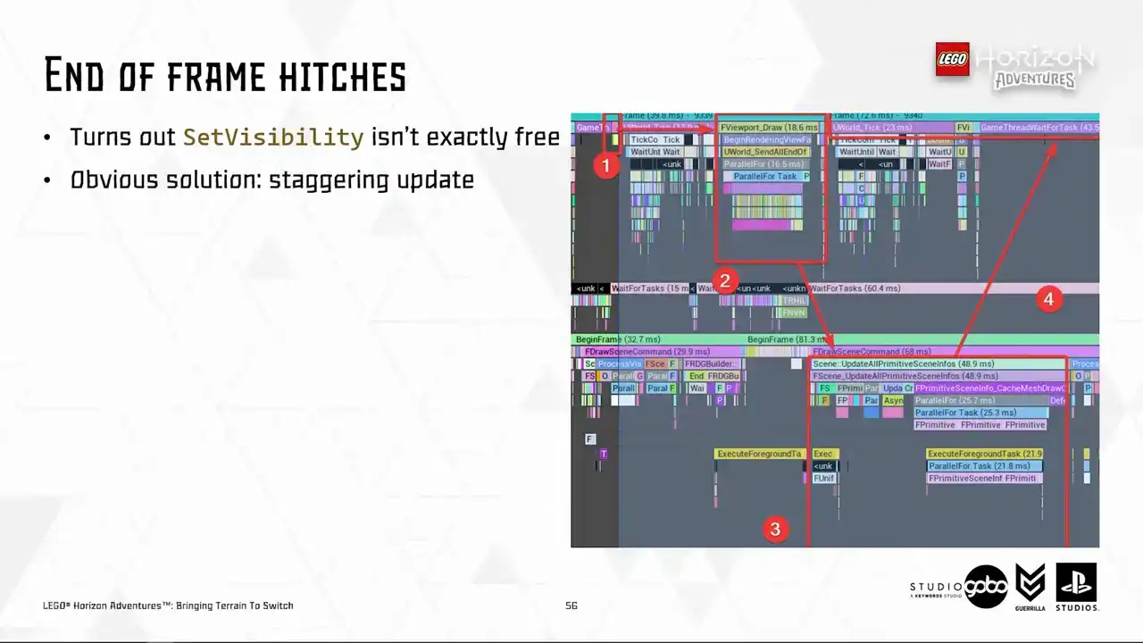
So let's say obvious solution is to cap the number of components being set visible or invisible every frame Or if you prefer the posh name staggering update But there a question almost all programmers out there will ask can we do any better than this
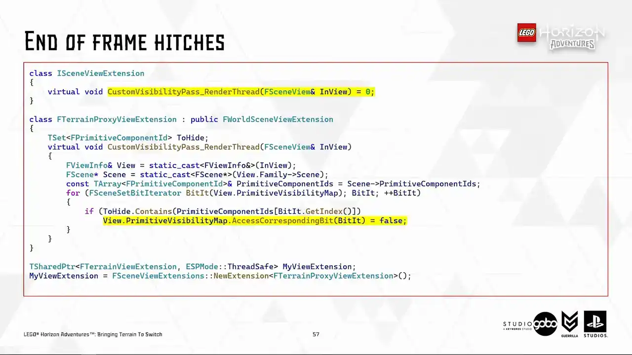
So I embark on this journey. I searched through the Unreal Code-based. I found out that something potentially useful, which is the Scene View's primitive visibility map, which get used in several different passes in the render thread,
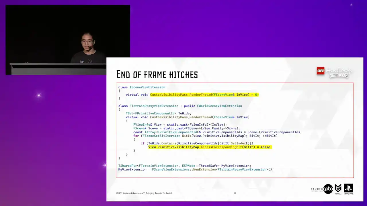
such as occlusion calling or fading primitive. So it seems like a natural fit to this. So I tried a custom visibility pass, which the SceneView extensions can override. This is running somewhere in the render thread where it makes sense.
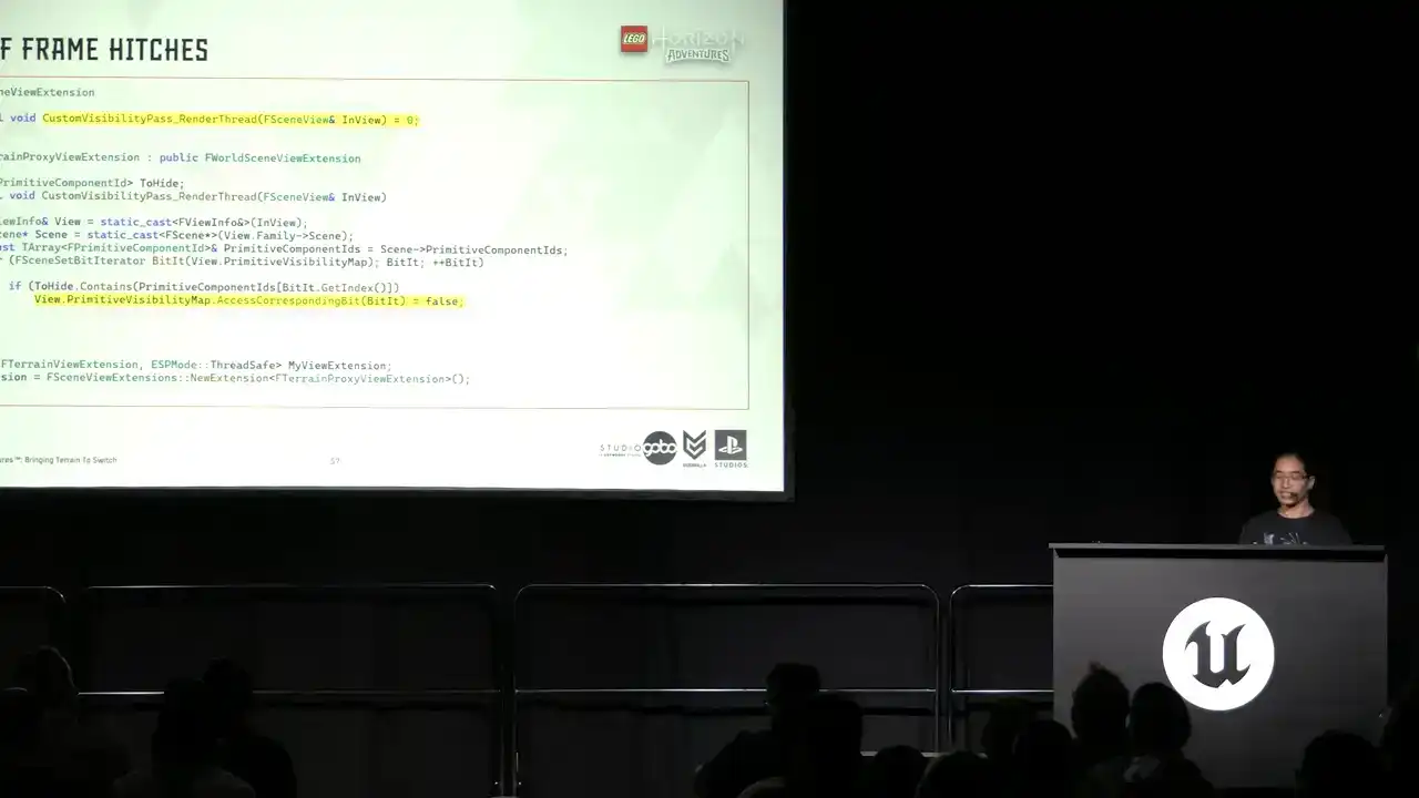
But the general idea is that in the terrain system, I don't issue set visibility calls, but to use that custom scene extension to show and hide the components.

The idea is that all components proxies are kept alive in the render thread. So what I hope to see is that now I don't have to pay the cost for allocating and setting up these scene proxies

every now and then. It would be less hitchy. So the answer is, well, yes and no.
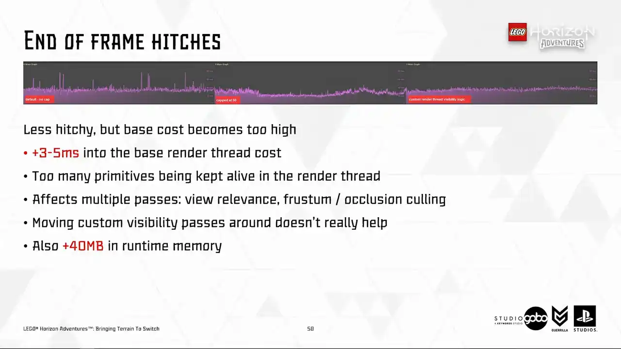
It does become less hitchy. Problem solved, right? But if you look into the far right, but the base cost is much higher due to more primitives being processed every frame. So we can try different solutions here, like moving the custom visibility parts around before or after the cooling passes
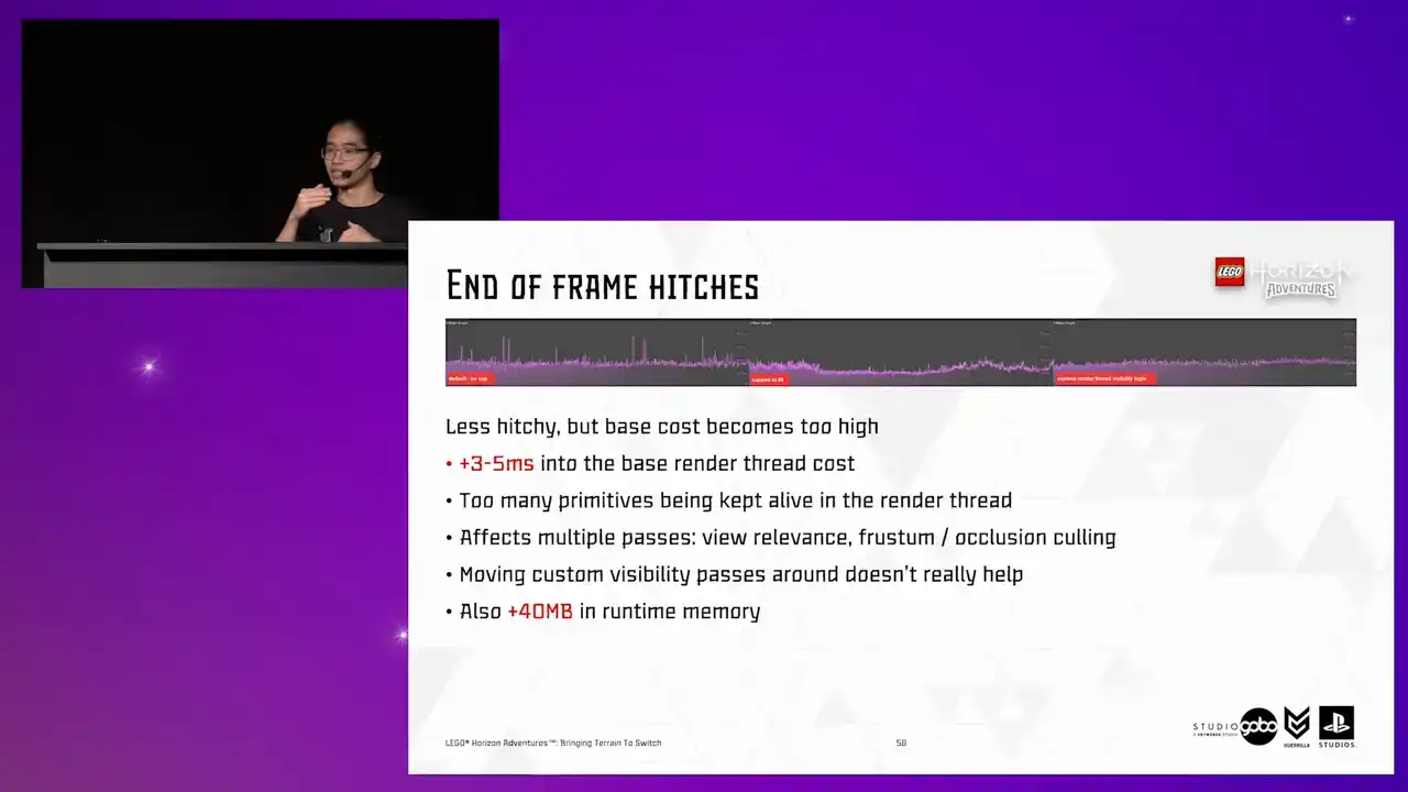
to reduce the number of primitives being processed. But that doesn't really help either, as we found on the RealDefi tests. the sheer number of primitives being processed is simply too high.
And also it asks like 40 megabytes into the runtime memory. So to answer the previous question, well, unfortunately not.

Okay, that's really it. That has been a while.
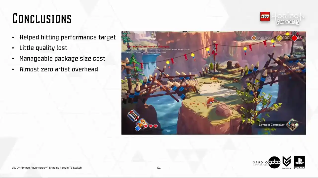
So what went well here is that we did hit the performance target with very little quality loss and our artists with their trained eyes cannot see any popping either. So good. The only price that we pay is some extra megabytes in the final package. That's not something too outrageous. And it is automated for the most part.
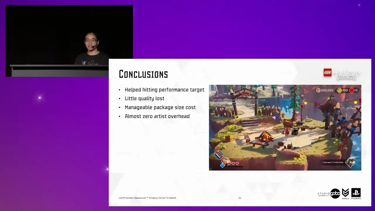
So zero artist overhead is required and artists can focus on doing what they are good at. Okay.

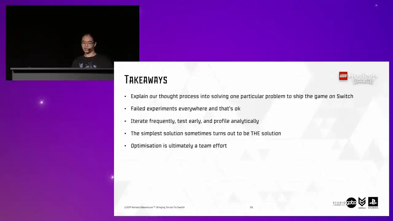
In closing, I have walked you through our process into solving one specific problem, taking into account all of our goals and constraints. And we sometimes stumbled into failed experiments, but in my opinion, that's okay,
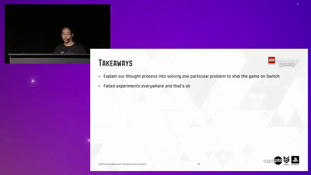
because sometimes it's just helpful to know a way that doesn't work as we expected. When it comes to optimization experimenting, I think nothing beats iteration. So as you can see, we did it frequently during this journey, and we look into the results in an analytical way to guide us to the next step.

Also, as you can see, our solutions are not rocket science at all. They are just very small, simple solutions stringed together into a bigger solution that works. But they will turn out to be the solution that we are looking for. And lastly, time for some sentimental remarks. Optimization is a team effort.
This is one of many problems that we solved to shape the game on Switch. and it already involves people from different disciplines, from tech art to environment art to engineering. So I would like to take this opportunity to thank them

to be awesome teammates and make all of this process enjoyable. Ah, I lied.
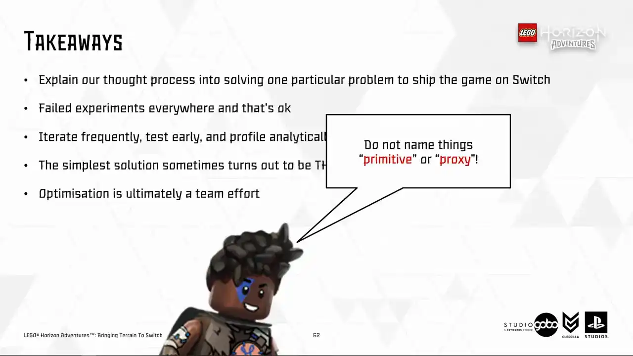
That was the last tip is to never name anything with common names like primitive or proxies to avoid name collisions. so here you can find the info about the talks my colleagues did in various other conferences

that i use as a reference today uh so this diet should be available online as well here's a qr code

that you can scan to download it um yep i believe i have a few minutes for questions but if we don't have the time for it, feel free to reach out to me via LinkedIn later. And yes, that's it.

Thank you for listening.